CAN COMMUNICATION SYSTEM(w/ Central Gateway ECU), Diagnostic DTC:U0100, U0129, U0293
| DTC Code | DTC Name |
|---|---|
| U0100 | Lost Communication with ECM / PCM "A" |
| U0129 | Lost Communication with Brake System Control Module |
| U0293 | Lost Communication with Hybrid Vehicle Control System |
DESCRIPTION
-
The hybrid vehicle control ECU communicates with the ECM and brake booster with master cylinder assembly (skid control ECU). When the hybrid vehicle control ECU does not receive data from the ECM or brake booster with master cylinder assembly (skid control ECU), the hybrid vehicle control ECU stores DTC U0100 or U0129.
-
The ECM communicates with the hybrid vehicle control ECU. When the ECM does not receive data from the hybrid vehicle control ECU, the ECM stores DTC U0293.
-
The brake booster with master cylinder assembly (skid control ECU) communicates with the hybrid vehicle control ECU. When the brake booster with master cylinder assembly (skid control ECU) does not receive data from the hybrid vehicle control ECU, the brake booster with master cylinder assembly (skid control ECU) stores DTC U0293.
| DTC No. | DTC Detection Condition | Trouble Area |
|---|---|---|
| U0100 | The hybrid vehicle control ECU does not receive data from the ECM. |
|
| U0129 | The hybrid vehicle control ECU does not receive data from the brake booster with master cylinder assembly (skid control ECU). |
|
| U0293 |
|
|
Tech Tips
This diagnostic procedure is for when DTC U0100, U0129 and U0293 are output at the same time.
WIRING DIAGRAM
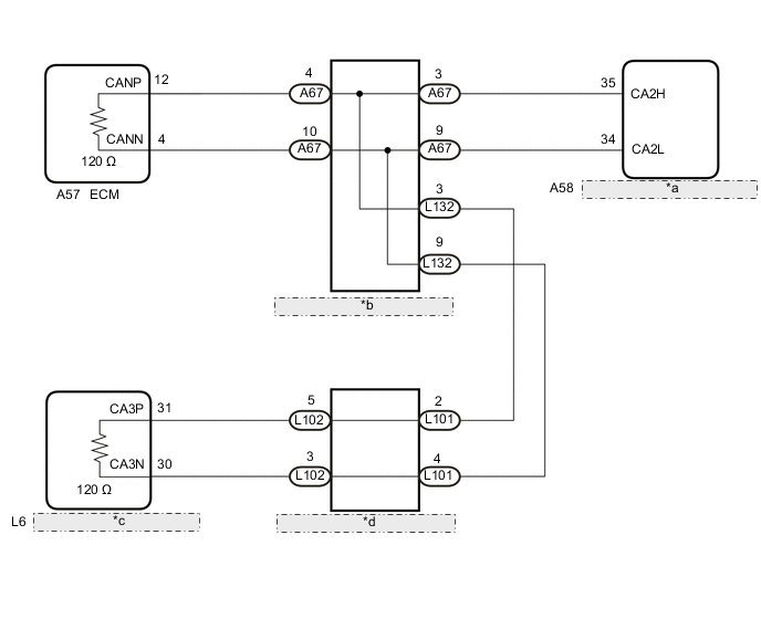
| *a | Brake Booster with Master Cylinder Assembly (Skid Control ECU) |
| *b | No. 1 CAN Junction Connector |
| *c | Hybrid Vehicle Control ECU |
| *d | No. 5 CAN Junction Connector |
CAUTION / NOTICE / HINT
Note
-
Before measuring the resistance of the CAN bus, turn the power switch off and leave the vehicle for 1 minute or more without operating the key or any switches, or opening or closing the doors. After that, disconnect the cable from the negative (-) auxiliary battery terminal and leave the vehicle for 1 minute or more before measuring the resistance.
-
After turning the power switch off, waiting time may be required before disconnecting the cable from the negative (-) auxiliary battery terminal. Therefore, make sure to read the disconnecting the cable from the negative (-) auxiliary battery terminal notices before proceeding with work Click here.
-
Because the order of diagnosis is important to allow correct diagnosis, make sure to begin troubleshooting using How to Proceed with Troubleshooting when CAN communication system related DTCs are output Click here.
-
After the repair, perform the CAN bus check and check that all the ECUs and sensors connected to the CAN communication system are displayed Click here.
Tech Tips
-
Before disconnecting related connectors for inspection, push in on each connector body to check that the connector is not loose or disconnected.
-
When a connector is disconnected, check that the terminals and connector body are not cracked, deformed or corroded.
PROCEDURE
-
RECONFIRM DTC OUTPUT
-
Reconfirm DTCs.
Tech Tips
If the hybrid vehicle control ECU outputs only DTC U0129, troubleshoot DTC U0129 and check the branch circuit of sub bus 15.
Result Result Proceed to The hybrid vehicle control ECU outputs DTC U0129 and other DTCs.
(GTS display: Hybrid Control)
A The hybrid vehicle control ECU outputs only DTC U0129.
(GTS display: Hybrid Control)
B
B 
GO TO DIAGNOSIS PROCEDURE INDICATED BY OUTPUT DTC Click here
A 
-
-
CHECK SUB BUS 15
-
Disconnect the cable from the negative (-) auxiliary battery terminal.
-

Text in Illustration *a Component with harness connected
(Hybrid Vehicle Control ECU)
Measure the resistance according to the value(s) in the table below.
Standard Resistance Tester Connection Condition Specified Condition Result L6-31 (CA3P) - L6-30 (CA3N) Cable disconnected from negative (-) auxiliary battery terminal 54 to 69 Ω Below 54 Ω:
Short circuit between bus lines
70 Ω or higher:
Open circuit in main bus lines
L6-31 (CA3P) - L6-4 (E12) Cable disconnected from negative (-) auxiliary battery terminal 200 Ω or higher Below 200 Ω:
CANH ground short
L6-30 (CA3N) - L6-4 (E12) Cable disconnected from negative (-) auxiliary battery terminal 200 Ω or higher Below 200 Ω:
CANL ground short
L6-31 (CA3P) - L6-3 (BATT) Cable disconnected from negative (-) auxiliary battery terminal 6 kΩ or higher Below 6 kΩ:
CANH +B short
L6-30 (CA3N) - L6-3 (BATT) Cable disconnected from negative (-) auxiliary battery terminal 6 kΩ or higher Below 6 kΩ:
CANL +B short
Tech Tips
-
When the value is as specified, clear and recheck for DTCs. When no DTCs are output, check for malfunctions such as damage or improper connection of the relevant connectors.
-
If DTCs are output although the bus circuit is normal and DTCs were cleared, replace the hybrid vehicle control ECU.
Result Result Proceed to OK A NG (Open circuit in CAN main bus lines) B NG (Short circuit between bus lines) C
-
NG (Ground short)
-
NG (+B short)
D -
A
REPLACE HYBRID VEHICLE CONTROL ECU Click here
C 
CHECK FOR SHORT IN SUB BUS 15 LINES (HYBRID VEHICLE CONTROL ECU) Click here
D
CHECK FOR SHORT IN SUB BUS 15 LINE (HYBRID VEHICLE CONTROL ECU) Click here
B
-
-
CHECK FOR OPEN IN SUB BUS 15 LINES (HYBRID VEHICLE CONTROL ECU)
-
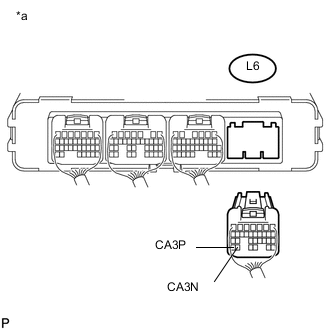
Text in Illustration *a Rear view of wire harness connector
(to Hybrid Vehicle Control ECU)
Disconnect the L6 hybrid vehicle control ECU connector.
-
Measure the resistance according to the value(s) in the table below.
Standard Resistance Tester Connection Condition Specified Condition L6-31 (CA3P) - L6-30 (CA3N) Cable disconnected from negative (-) auxiliary battery terminal 108 to 132 Ω
OK
REPLACE HYBRID VEHICLE CONTROL ECU Click here
NG
-
-
CHECK FOR OPEN IN SUB BUS 15 LINES (NO. 5 CAN JUNCTION CONNECTOR - NO. 1 CAN JUNCTION CONNECTOR)
-
Reconnect the L6 hybrid vehicle control ECU connector.
-
Disconnect the L101 wire harness connector from the No. 5 CAN junction connector (instrument panel connector holder left side).
-
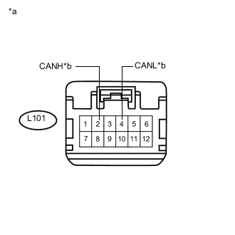
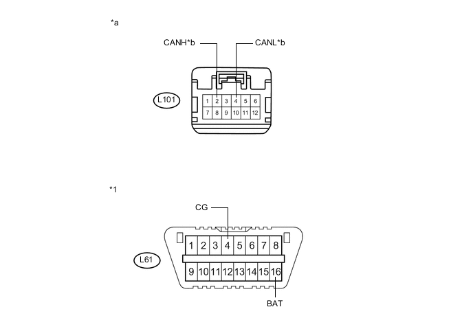
Text in Illustration *a Front view of wire harness connector
(to No. 5 CAN Junction Connector)
*b to No. 1 CAN Junction Connector Measure the resistance according to the value(s) in the table below.
Standard Resistance Tester Connection Condition Specified Condition L101-2 (CANH) - L101-4 (CANL) Cable disconnected from negative (-) auxiliary battery terminal 108 to 132 Ω
NG
CHECK FOR OPEN IN SUB BUS 15 LINES (NO. 1 CAN JUNCTION CONNECTOR - NO. 5 CAN JUNCTION CONNECTOR) Click here
OK
-
-
CHECK FOR OPEN IN SUB BUS 15 LINES (NO. 5 CAN JUNCTION CONNECTOR - HYBRID VEHICLE CONTROL ECU)
-
Reconnect the L101 wire harness connector to the No. 5 CAN junction connector (instrument panel connector holder left side).
-
Disconnect the L102 wire harness connector from the No. 5 CAN junction connector (instrument panel connector holder right side).
-
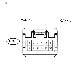
Text in Illustration *a Front view of wire harness connector
(to No. 5 CAN Junction Connector)
*b to Hybrid Vehicle Control ECU Measure the resistance according to the value(s) in the table below.
Standard Resistance Tester Connection Condition Specified Condition L102-5 (CANH) - L102-3 (CANL) Cable disconnected from negative (-) auxiliary battery terminal 108 to 132 Ω
OK
REPLACE NO. 5 CAN JUNCTION CONNECTOR
NG
REPAIR OR REPLACE CAN MAIN BUS LINES OR CONNECTOR (NO. 5 CAN JUNCTION CONNECTOR - HYBRID VEHICLE CONTROL ECU)
-
-
CHECK FOR OPEN IN SUB BUS 15 LINES (NO. 1 CAN JUNCTION CONNECTOR - NO. 5 CAN JUNCTION CONNECTOR)
-
Reconnect the L101 wire harness connector to the No. 5 CAN junction connector (instrument panel connector holder left side).
-
Disconnect the L132 wire harness connector from the No. 1 CAN junction connector (instrument panel wire side).
-
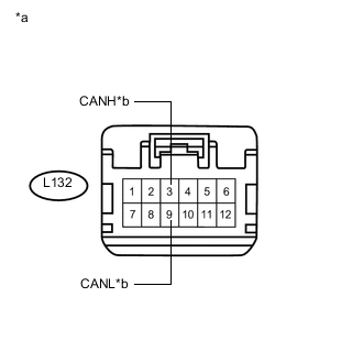
Text in Illustration *a Front view of wire harness connector
(to No. 1 CAN Junction Connector)
*b to No. 5 CAN Junction Connector Measure the resistance according to the value(s) in the table below.
Standard Resistance Tester Connection Condition Specified Condition L132-3 (CANH) - L132-9 (CANL) Cable disconnected from negative (-) auxiliary battery terminal 108 to 132 Ω
NG
REPAIR OR REPLACE CAN MAIN BUS LINES OR CONNECTOR (NO. 1 CAN JUNCTION CONNECTOR - NO. 5 CAN JUNCTION CONNECTOR)
OK
-
-
CHECK FOR OPEN IN SUB BUS 15 LINES (NO. 1 CAN JUNCTION CONNECTOR - ECM)
-
Reconnect the L132 wire harness connector to the No. 1 CAN junction connector (instrument panel wire side).
-
Disconnect the A67 wire harness connector from the No. 1 CAN junction connector (engine room main wire side).
-
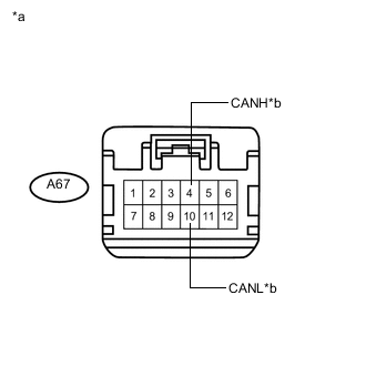
Text in Illustration *a Front view of wire harness connector
(to No. 1 CAN Junction Connector)
*b to ECM Measure the resistance according to the value(s) in the table below.
Standard Resistance Tester Connection Condition Specified Condition A67-4 (CANH) - A67-10 (CANL) Cable disconnected from negative (-) auxiliary battery terminal 108 to 132 Ω
OK
REPLACE NO. 1 CAN JUNCTION CONNECTOR
NG
-
-
CHECK FOR OPEN IN SUB BUS 15 LINES (ECM)
-
Reconnect the A67 wire harness connector to the No. 1 CAN junction connector (engine room main wire side).
-
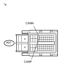
Text in Illustration *a Front view of wire harness connector
(to ECM)
Disconnect the A57 ECM connector.
-
Measure the resistance according to the value(s) in the table below.
Standard Resistance Tester Connection Condition Specified Condition A57-12 (CANP) - A57-4 (CANN) Cable disconnected from negative (-) auxiliary battery terminal 108 to 132 Ω
OK
REPLACE ECM Click here
NG
REPAIR OR REPLACE CAN MAIN BUS LINES OR CONNECTOR (NO. 1 CAN JUNCTION CONNECTOR - ECM)
-
-
CHECK FOR SHORT IN SUB BUS 15 LINES (HYBRID VEHICLE CONTROL ECU)
-
Text in Illustration *a Rear view of wire harness connector
(to Hybrid Vehicle Control ECU)
Disconnect the L6 hybrid vehicle control ECU connector.
-
Measure the resistance according to the value(s) in the table below.
Standard Resistance Tester Connection Condition Specified Condition L6-31 (CA3P) - L6-30 (CA3N) Cable disconnected from negative (-) auxiliary battery terminal 108 to 132 Ω
OK
REPLACE HYBRID VEHICLE CONTROL ECU Click here
NG
-
-
CHECK FOR SHORT IN SUB BUS 15 LINES (NO. 5 CAN JUNCTION CONNECTOR - HYBRID VEHICLE CONTROL ECU)
-
Reconnect the L6 hybrid vehicle control ECU connector.
-
Disconnect the L102 wire harness connector from the No. 5 CAN junction connector (instrument panel connector holder right side).
-
Text in Illustration *a Front view of wire harness connector
(to No. 5 CAN Junction Connector)
*b to Hybrid Vehicle Control ECU Measure the resistance according to the value(s) in the table below.
Standard Resistance Tester Connection Condition Specified Condition L102-5 (CANH) - L102-3 (CANL) Cable disconnected from negative (-) auxiliary battery terminal 108 to 132 Ω
NG
REPAIR OR REPLACE CAN MAIN BUS LINES OR CONNECTOR (NO. 5 CAN JUNCTION CONNECTOR - HYBRID VEHICLE CONTROL ECU)
OK
-
-
CHECK FOR SHORT IN SUB BUS 15 LINES (NO. 5 CAN JUNCTION CONNECTOR)
-
Disconnect the L101 wire harness connector from the No. 5 CAN junction connector (instrument panel connector holder left side).
-
Text in Illustration *a Front view of wire harness connector
(to No. 5 CAN Junction Connector)
*b to No. 1 CAN Junction Connector Measure the resistance according to the value(s) in the table below.
Standard Resistance Tester Connection Condition Specified Condition L101-2 (CANH) - L101-4 (CANL) Cable disconnected from negative (-) auxiliary battery terminal 108 to 132 Ω
OK
REPLACE NO. 5 CAN JUNCTION CONNECTOR
NG
-
-
CHECK FOR SHORT IN SUB BUS 15 LINES (NO. 1 CAN JUNCTION CONNECTOR - NO. 5 CAN JUNCTION CONNECTOR)
-
Disconnect the L132 wire harness connector from the No. 1 CAN junction connector (instrument panel wire side).
-
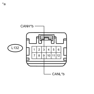
Text in Illustration *a Front view of wire harness connector
(to No. 1 CAN Junction Connector)
*b to No. 5 CAN Junction Connector Measure the resistance according to the value(s) in the table below.
Standard Resistance Tester Connection Condition Specified Condition L132-3 (CANH) - L132-9 (CANL) Cable disconnected from negative (-) auxiliary battery terminal 1 MΩ or higher
NG
REPAIR OR REPLACE CAN MAIN BUS LINES OR CONNECTOR (NO. 1 CAN JUNCTION CONNECTOR - NO. 5 CAN JUNCTION CONNECTOR)
OK
-
-
CHECK FOR SHORT IN SUB BUS 15 LINES (NO. 1 CAN JUNCTION CONNECTOR)
-
Disconnect the A67 wire harness connector from the No. 1 CAN junction connector (engine room main wire side).
-
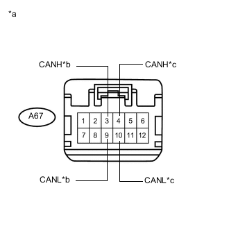
Text in Illustration *a Front view of wire harness connector
(to No. 1 CAN Junction Connector)
*b to Brake booster with master cylinder assembly (Skid control ECU) *c to ECM Measure the resistance according to the value(s) in the table below.
Standard Resistance Tester Connection Condition Specified Condition A67-3 (CANH) - A67-9 (CANL) Cable disconnected from negative (-) auxiliary battery terminal 200 Ω or higher A67-4 (CANH) - A67-10 (CANL) Cable disconnected from negative (-) auxiliary battery terminal 108 to 132 Ω Result Result Proceed to OK A NG (ECM CAN main bus lines) B NG (Brake booster with master cylinder assembly (skid control ECU) CAN branch lines) C
A
REPLACE NO. 1 CAN JUNCTION CONNECTOR
C
CHECK FOR SHORT IN SUB BUS 15 LINES (BRAKE BOOSTER WITH MASTER CYLINDER ASSEMBLY (SKID CONTROL ECU) Click here
B
-
-
CHECK FOR SHORT IN SUB BUS 15 LINES (ECM)
-
Text in Illustration *a Front view of wire harness connector
(to ECM)
Disconnect the A57 ECM connector.
-
Measure the resistance according to the value(s) in the table below.
Standard Resistance Tester Connection Condition Specified Condition A57-12 (CANP) - A57-4 (CANN) Cable disconnected from negative (-) auxiliary battery terminal 1 MΩ or higher
OK
REPLACE ECM Click here
NG
REPAIR OR REPLACE CAN MAIN BUS LINES OR CONNECTOR (NO. 1 CAN JUNCTION CONNECTOR - ECM)
-
-
CHECK FOR SHORT IN SUB BUS 15 LINES (BRAKE BOOSTER WITH MASTER CYLINDER ASSEMBLY (SKID CONTROL ECU)
-
Disconnect the A58 brake booster with master cylinder assembly (skid control ECU) connector.
-
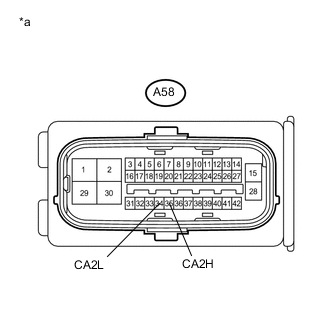
Text in Illustration *a Front view of wire harness connector
(to Brake Booster with Master Cylinder Assembly (Skid Control ECU))
Measure the resistance according to the value(s) in the table below.
Standard Resistance Tester Connection Condition Specified Condition A58-35 (CA2H) - A58-34 (CA2L) Cable disconnected from negative (-) auxiliary battery terminal 1 MΩ or higher Result Result Proceed to OK (for LHD) A OK (for RHD) B NG C
A
REPLACE BRAKE BOOSTER WITH MASTER CYLINDER ASSEMBLY (SKID CONTROL ECU) Click here
B
REPLACE BRAKE BOOSTER WITH MASTER CYLINDER ASSEMBLY (SKID CONTROL ECU) Click here
C
REPAIR OR REPLACE CAN BRANCH LINES OR CONNECTOR (NO. 1 CAN JUNCTION CONNECTOR - BRAKE BOOSTER WITH MASTER CYLINDER ASSEMBLY (SKID CONTROL ECU))
-
-
CHECK FOR SHORT IN SUB BUS 15 LINE (HYBRID VEHICLE CONTROL ECU)
-
Disconnect the L6 hybrid vehicle control ECU connector.
-
Measure the resistance according to the value(s) in the table below.
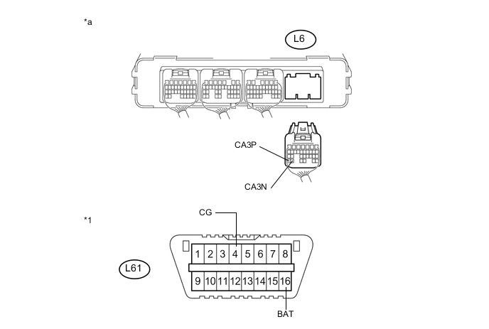
Standard Resistance Tester Connection Condition Specified Condition Result L6-31 (CA3P) - L61-4 (CG) Cable disconnected from negative (-) auxiliary battery terminal 200 Ω or higher Inspection for CANH ground short L6-30 (CA3N) - L61-4 (CG) Cable disconnected from negative (-) auxiliary battery terminal 200 Ω or higher Inspection for CANL ground short L6-31 (CA3P) - L61-16 (BAT) Cable disconnected from negative (-) auxiliary battery terminal 6 kΩ or higher Inspection for CANH +B short L6-30 (CA3N) - L61-16 (BAT) Cable disconnected from negative (-) auxiliary battery terminal 6 kΩ or higher Inspection for CANL +B short Text in Illustration *1 DLC3 - - *a Rear view of wire harness connector
(to Hybrid Vehicle Control ECU)
- - Tech Tips
-
It is only necessary to perform the inspection in the above table for the result (short circuit) that was obtained in the Check Sub Bus 15 inspection.
-
Find the necessary inspection from the Result column that matches the result in the Result column from the Check Sub Bus 15 inspection.
-
OK
REPLACE HYBRID VEHICLE CONTROL ECU Click here
NG
-
-
CHECK FOR SHORT IN SUB BUS 15 LINE (NO. 5 CAN JUNCTION CONNECTOR - HYBRID VEHICLE CONTROL ECU)
-
Disconnect the L102 wire harness connector from the No. 5 CAN junction connector (instrument panel connector holder right side).
-
Measure the resistance according to the value(s) in the table below.
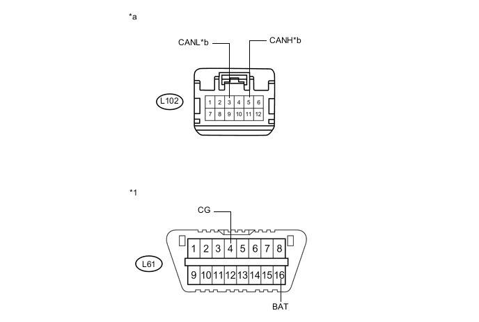
Standard Resistance Tester Connection Condition Specified Condition Result L102-5 (CANH) - L61-4 (CG) Cable disconnected from negative (-) auxiliary battery terminal 200 Ω or higher Inspection for CANH ground short L102-3 (CANL) - L61-4 (CG) Cable disconnected from negative (-) auxiliary battery terminal 200 Ω or higher Inspection for CANL ground short L102-5 (CANH) - L61-16 (BAT) Cable disconnected from negative (-) auxiliary battery terminal 6 kΩ or higher Inspection for CANH +B short L102-3 (CANL) - L61-16 (BAT) Cable disconnected from negative (-) auxiliary battery terminal 6 kΩ or higher Inspection for CANL +B short Text in Illustration *1 DLC3 - - *a Front view of wire harness connector
(to No. 5 CAN Junction Connector)
*b to Hybrid vehicle control ECU Tech Tips
-
It is only necessary to perform the inspection in the above table for the result (short circuit) that was obtained in the Check Sub Bus 15 inspection.
-
Find the necessary inspection from the Result column that matches the result in the Result column from the Check Sub Bus 15 inspection.
-
NG
REPAIR OR REPLACE CAN MAIN BUS LINE OR CONNECTOR (NO. 5 CAN JUNCTION CONNECTOR - HYBRID VEHICLE CONTROL ECU)
OK
-
-
CHECK FOR SHORT IN SUB BUS 15 LINE (NO. 5 CAN JUNCTION CONNECTOR)
-
Disconnect the L101 wire harness connector from the No. 5 CAN junction connector (instrument panel connector holder left side).
-
Measure the resistance according to the value(s) in the table below.
Standard Resistance Tester Connection Condition Specified Condition Result L101-2 (CANH) - L61-4 (CG) Cable disconnected from negative (-) auxiliary battery terminal 200 Ω or higher Inspection for CANH ground short L101-4 (CANL) - L61-4 (CG) Cable disconnected from negative (-) auxiliary battery terminal 200 Ω or higher Inspection for CANL ground short L101-2 (CANH) - L61-16 (BAT) Cable disconnected from negative (-) auxiliary battery terminal 6 kΩ or higher Inspection for CANH +B short L101-4 (CANL) - L61-16 (BAT) Cable disconnected from negative (-) auxiliary battery terminal 6 kΩ or higher Inspection for CANL +B short Text in Illustration *1 DLC3 - - *a Front view of wire harness connector
(to No. 5 CAN Junction Connector)
*b to No. 1 CAN Junction Connector Tech Tips
-
It is only necessary to perform the inspection in the above table for the result (short circuit) that was obtained in the Check Sub Bus 15 inspection.
-
Find the necessary inspection from the Result column that matches the result in the Result column from the Check Sub Bus 15 inspection.
-
OK
REPLACE NO. 5 CAN JUNCTION CONNECTOR
NG
-
-
CHECK FOR SHORT IN SUB BUS 15 LINE (NO. 1 CAN JUNCTION CONNECTOR - NO. 5 CAN JUNCTION CONNECTOR)
-
Disconnect the L132 wire harness connector from the No. 1 CAN junction connector (instrument panel wire side).
-
Measure the resistance according to the value(s) in the table below.
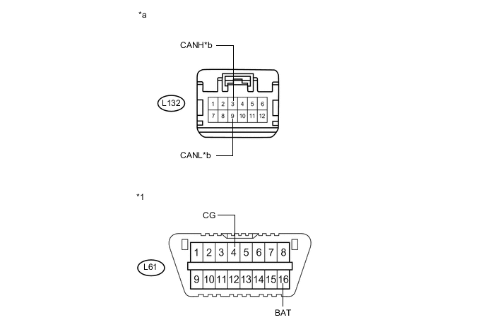
Standard Resistance Tester Connection Condition Specified Condition Result L132-3 (CANH) - L61-4 (CG) Cable disconnected from negative (-) auxiliary battery terminal 200 Ω or higher Inspection for CANH ground short L132-9 (CANL) - L61-4 (CG) Cable disconnected from negative (-) auxiliary battery terminal 200 Ω or higher Inspection for CANL ground short L132-3 (CANH) - L61-16 (BAT) Cable disconnected from negative (-) auxiliary battery terminal 6 kΩ or higher Inspection for CANH +B short L132-9 (CANL) - L61-16 (BAT) Cable disconnected from negative (-) auxiliary battery terminal 6 kΩ or higher Inspection for CANL +B short Tech Tips
-
It is only necessary to perform the inspection in the above table for the result (short circuit) that was obtained in the Check Sub Bus 15 inspection.
-
Find the necessary inspection from the Result column that matches the result in the Result column from the Check Sub Bus 15 inspection.
Text in Illustration *1 DLC3 - - *a Front view of wire harness connector
(to No. 1 CAN Junction Connector)
*b to No. 5 CAN Junction Connector -
NG
REPAIR OR REPLACE CAN MAIN BUS LINE OR CONNECTOR (NO. 1 CAN JUNCTION CONNECTOR - NO. 5 CAN JUNCTION CONNECTOR)
OK
-
-
CHECK FOR SHORT IN SUB BUS 15 LINE (NO. 1 CAN JUNCTION CONNECTOR)
-
Disconnect the A67 wire harness connector from the No. 1 CAN junction connector (engine room main wire side).
-
Measure the resistance according to the value(s) in the table below.
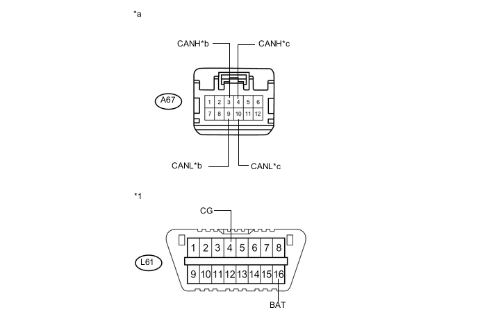
Standard Resistance Tester Connection Condition Specified Condition Result Connected to A67-3 (CANH) - L61-4 (CG) Cable disconnected from negative (-) auxiliary battery terminal 200 Ω or higher Inspection for CANH ground short Brake booster with master cylinder assembly (skid control ECU) A67-9 (CANL) - L61-4 (CG) Cable disconnected from negative (-) auxiliary battery terminal 200 Ω or higher Inspection for CANL ground short A67-4 (CANH) - L61-4 (CG) Cable disconnected from negative (-) auxiliary battery terminal 200 Ω or higher Inspection for CANH ground short ECM A67-10 (CANL) - L61-4 (CG) Cable disconnected from negative (-) auxiliary battery terminal 200 Ω or higher Inspection for CANL ground short A67-3 (CANH) - L61-16 (BAT) Cable disconnected from negative (-) auxiliary battery terminal 6 kΩ or higher Inspection for CANH +B short Brake booster with master cylinder assembly (skid control ECU) A67-9 (CANL) - L61-16 (BAT) Cable disconnected from negative (-) auxiliary battery terminal 6 kΩ or higher Inspection for CANL +B short A67-4 (CANH) - L61-16 (BAT) Cable disconnected from negative (-) auxiliary battery terminal 6 kΩ or higher Inspection for CANH +B short ECM A67-10 (CANL) - L61-16 (BAT) Cable disconnected from negative (-) auxiliary battery terminal 6 kΩ or higher Inspection for CANL +B short Text in Illustration *1 DLC3 - - *a Front view of wire harness connector
(to No. 1 CAN Junction Connector)
*b to Brake booster with master cylinder assembly (Skid control ECU) *c to ECM - - Tech Tips
-
It is only necessary to perform the inspection in the above table for the result (short circuit) that was obtained in the Check Sub Bus 15 inspection.
-
Find the necessary inspection from the Result column that matches the result in the Result column from the Check Sub Bus 15 inspection.
-
OK
REPLACE NO. 1 CAN JUNCTION CONNECTOR
NG
-
-
CHECK SUB BUS 15 LINE (ECU OR SENSOR)
-
Reconnect all wire harness connectors.
-
Disconnect the connector that includes terminals CANH and CANL from the ECU or sensor to which the bus line shorted to +B or shorted to GND is connected.
-
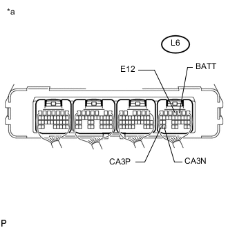
Text in Illustration *a Component with harness connected
(Hybrid Vehicle Control ECU)
Measure the resistance according to the value(s) in the table below.
Standard Resistance Tester Connection Condition Specified Condition Result L6-31 (CA3P) - L6-4 (E12) Cable disconnected from negative (-) auxiliary battery terminal 200 Ω or higher Below 200 Ω:
CANH ground short
L6-30 (CA3N) - L6-4 (E12) Cable disconnected from negative (-) auxiliary battery terminal 200 Ω or higher Below 200 Ω:
CANL ground short
L6-31 (CA3P) - L6-3 (BATT) Cable disconnected from negative (-) auxiliary battery terminal 6 kΩ or higher Below 6 kΩ:
CANH +B short
L6-30 (CA3N) - L6-3 (BATT) Cable disconnected from negative (-) auxiliary battery terminal 6 kΩ or higher Below 6 kΩ:
CANL +B short
Tech Tips
-
It is only necessary to perform the inspection in the above table for the result (short circuit) that was obtained in the Check Sub Bus 15 inspection.
-
Find the necessary inspection from the Result column that matches the result in the Result column from the Check Sub Bus 15 inspection.
-
OK
REPLACE CORRESPONDING ECU OR SENSOR
NG
REPAIR OR REPLACE CORRESPONDING ECU OR SENSOR
-