WIPER AND WASHER SYSTEM(w/o Rain Sensor) SYSTEM DESCRIPTION
WASHER-LINKED OPERATION
This system operates the front wipers at low speed immediately after spraying a jet of washer fluid when the front washer switch is turned on for 0.3 seconds or more.
The system operates the front wipers at low speed for approximately 2.2 seconds and then stops operation when the washer switch is turned on for 1.5 seconds or more.
FRONT WIPER INTERMITTENT OPERATION (w/ Intermittent Timing)
The system operates the front wipers once in approximately 1.6 to 10.7 seconds when the windshield wiper switch asse,bly is turned to the INT position. The intermittent time can be adjusted from 1.6 to 10.7 seconds by using the intermittent time adjust dial.
If the front wiper switch is turned to the INT position, current flows from the already charged capacitor C1 through terminals INT1 and INT2 of the front wiper switch to Tr1 (transistor). When Tr1 turns on, current flows from terminal +S of the front wiper switch to terminal +1 of the front wiper switch, to terminal +1 of the wiper motor, to the wiper motor and finally to ground, causing the wiper motor to operate. At the same time, current flows from capacitor C1 to terminal INT1 of the front wiper switch and then INT2. When the current flow from capacitor C1 ends, Tr1 turns off to turn off the relay contact and halt the wiper motor.
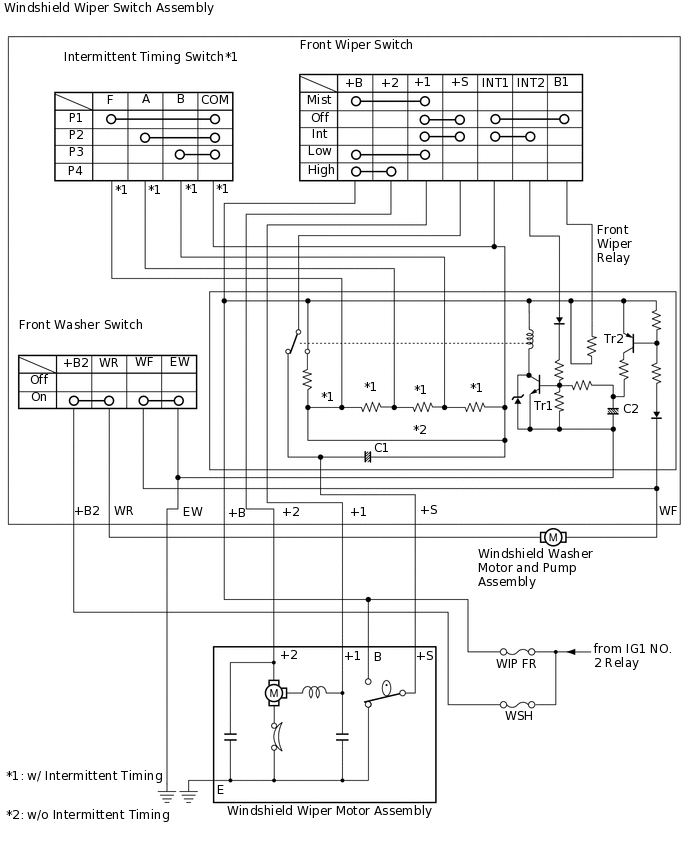
When the relay contact turns off, capacitor C1 begins to charge again and Tr1 remains off until charging has been completed. This period corresponds to the intermittent time. When capacitor C1 is fully charged, Tr1 turns on and then the relay contact turns on, causing the motor to operate again. This cycle is the intermittent operation.The intermittent time can be adjusted by using the intermittent time adjust dial (variable resistor) to change the charge time of capacitor C1.
REAR WIPER INTERMITTENT OPERATION
When the rear wiper switch is turned to the INT position, current flows from the capacitor of the intermittent operation control circuit to turn on the transistor. Current flows from terminal +B of the rear wiper relay to the relay coil, to the transistor, to terminal C1 of the rear wiper relay, to terminal C1R of the rear wiper switch and finally to ground, causing the relay contact point to turn on.
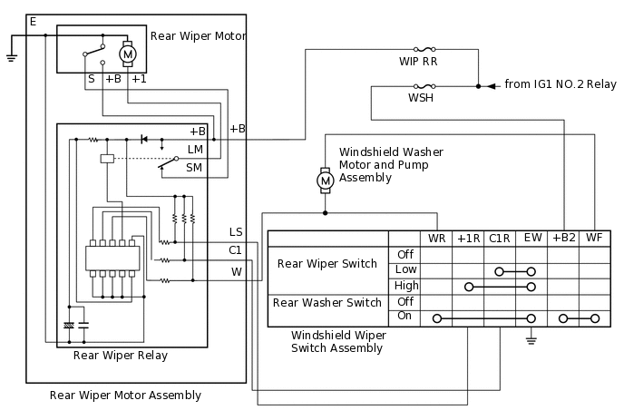
When the relay contact turns on, current flows from terminal +B of the rear wiper relay to the relay contact, to terminal LM of the rear wiper relay, to terminal +1 of the rear wiper motor, to the rear wiper motor and finally to ground, causing the rear wiper motor to operate. The transistor turns off immediately after the rear wiper motor operation as the current flow from the capacitor ends, causing the relay contact to turn off.
Even when the relay contact turns off, current flows from terminal +B of the rear wiper motor to the relay contact in the rear wiper motor, to terminal S of the rear wiper motor, to terminal SM of the rear wiper relay, to the contact of the rear wiper relay, to terminal LM of the rear wiper relay, to terminal +1 of the rear wiper motor and finally to ground, causing the rear wiper motor to operate, until the rear wiper motor stops at the automatic stop position. The rear wiper motor stops at the automatic stop position as the relay contact in the rear wiper motor turns off.
The capacitor in the intermittent operation control circuit is charged in approximately 12 seconds after the current flow ends. After the charge is completed, current starts flowing again to turn on the transistor, causing the relay contact to turn on.
This cycle of current flow and charging described above is the intermittent operation.
HEADLIGHT CLEANER SYSTEM (w/ Headlight Cleancer System)
The headlight cleaner system operates only one time for every 5 times the windshield washer switch is operated.
Headlight Beam (LO/HI)
Washer Switch (Windshield Wiper Switch Assembly)
On (First Time)
On (Second Time to Fourth Time)
On (Sixth Time and Every Additional Fifth Time)
On
Activated
Not Activated
Activated
Off
Not Activated
Not Activated
Not Activated
WASHER FLUID LEVEL WARNING (w/ Panic Switch)
When the volume of washer fluid decreases to below a certain level (when the level warning switch is turned on), the combination meter assembly warns the driver through the illumination of the master warning light on the washer warning light.