GENERATOR(for 100A Type) REASSEMBLY
PROCEDURE
INSTALL GENERATOR DRIVE END FRAME BEARING
-
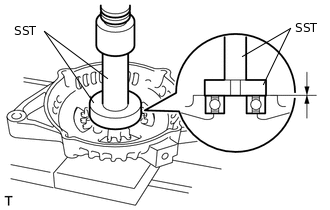
Using SST and a press, press in a new generator drive end frame bearing.
09950-60010
09951-00470
09950-70010
09951-07100
-
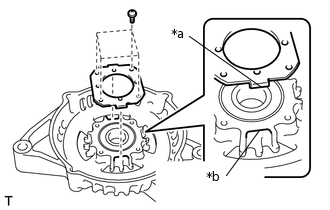
*a
Tab
*b
Cutout
Fit the tabs on the retainer plate into the cutouts on the generator drive end frame.
Install the retainer plate to the generator drive end frame with the 4 screws.
2.3 N*m
23 kgf*cm
20 in.*lbf
-
INSTALL GENERATOR ROTOR ASSEMBLY
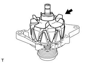
Place the generator drive end frame on the generator with clutch pulley.
Install the generator rotor assembly to the generator drive end frame.
INSTALL GENERATOR COIL ASSEMBLY
-
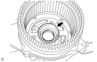
Install the bearing cover packing.
Tip:Align the protrusion of the bearing cover packing with the groove of the generator coil assembly when installing.
-
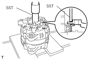
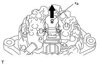
Using SST and a press, slowly press the generator coil assembly to install it.
09612-70100
09612-07240
-
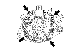
Install the 4 bolts.
5.6 N*m
57 kgf*cm
50 in.*lbf
-
INSTALL GENERATOR BRUSH HOLDER ASSEMBLY
-
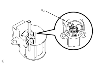
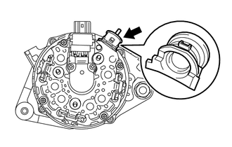
*a
Pin (1.0 mm)
While pushing the 2 brushes into the generator brush holder assembly, insert a 1.0 mm (0.0394 in.) pin into the generator brush holder assembly hole.
-
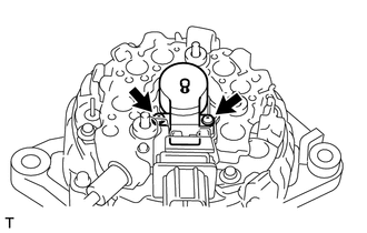
Install the generator brush holder assembly to the generator coil assembly with the 2 screws.
1.8 N*m
18 kgf*cm
16 in.*lbf
-
*a
Pin (1.0 mm)
Pull out the pin from the generator brush holder assembly hole.
-
INSTALL GENERATOR TERMINAL INSULATOR
-
Install the generator terminal insulator to the generator coil assembly.
Note:Be sure to install the generator terminal insulator in the correct direction.
-
INSTALL GENERATOR REAR END COVER
-
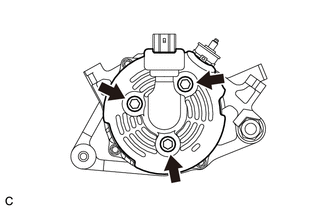
Install the generator rear end cover to the generator coil assembly with the 3 bolts.
4.6 N*m
47 kgf*cm
41 in.*lbf
-
INSTALL GENERATOR WITH CLUTCH PULLEY
Temporarily install the generator with clutch pulley to the rotor shaft.
Secure the generator drive end frame in a vise between aluminum plates.
-
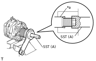
*a
Rotor Shaft
Place the rotor shaft end into SST (A).
09820-63021
-
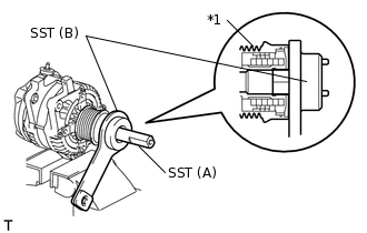
*1
Generator with Clutch Pulley
Fit SST (B) to the generator with clutch pulley.
-
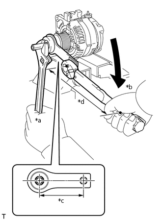
*a
Hold
*b
Turn
*c
Length of SST 100 mm (3.94 in.)
*d
Length of Torque Wrench 255 mm (10.0 in.)
Tighten the generator with clutch pulley by turning SST (B) as shown in the illustration.
without SST [Torque (N*m(kgf*cm, ft.*lbf))]
80 N*m
816 kgf*cm
59 ft.*lbf
with SST [Reading of Torque wrench (N*m(kgf*cm, ft.*lbf))]
57 N*m
581 kgf*cm
42 ft.*lbf
Tip:The "with SST" torque value is effective when SST is parallel to the torque wrench.
The "with SST" torque value is effective when using SST with a fulcrum length of 100 mm (3.94 in.).
The "with SST" torque value is effective when using a torque wrench with a fulcrum length of 255 mm (10.0 in.).
If using a torque wrench with a different length, or connecting the torque wrench and SST at an angle, refer to the alternate torque values.
Remove SST from the generator with clutch pulley.
Check that the generator with clutch pulley rotates smoothly.
INSTALL GENERATOR PULLEY CAP
Install a new generator pulley cap to the generator with clutch pulley.