INTERCOOLER INSTALLATION
-
INSTALL INTERCOOLER ASSEMBLY
-
Temporarily install the intercooler with the 3 bolts.
-
Connect the No. 3 air hose and tighten the hose clamp as shown in the illustration.
- Torque:
- 6.0 N*m { 61 kgf*cm, 53 in.*lbf }
Note
-
Insert the hose until it is flush with the pipe spool end, install the clip and then check that it is securely connected.
-
Check that the hose does not interfere with any other parts.
-
Check that the hose is not twisted.
-
Connect the No. 2 air hose and tighten the hose clamp as shown in the illustration.
- Torque:
- 6.0 N*m { 61 kgf*cm, 53 in.*lbf }
Note
-
Insert the hose until it is flush with the pipe spool end, install the clip and then check that it is securely connected.
-
Check that the hose does not interfere with any other parts.
-
Check that the hose is not twisted.
-
Tighten the 3 bolts.
- Torque:
- 18 N*m { 178 kgf*cm, 13 ft.*lbf }
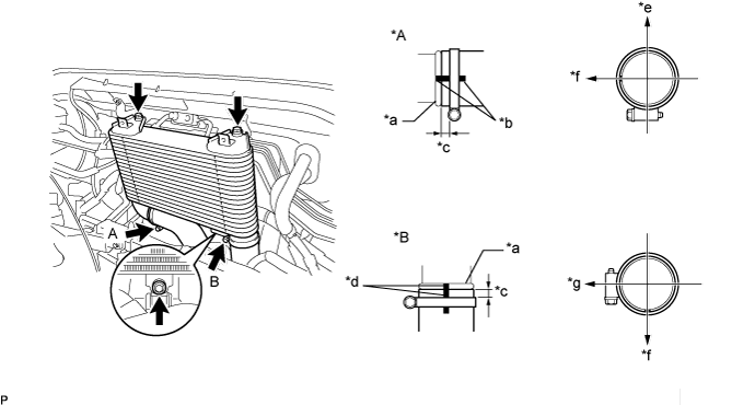
Text in Illustration *A View A *B View B *a Spool *b Yellow Paint *c 2.0 to 7.0 mm (0.079 to 0.276 in.) *d Blue Paint *e Upper Side *f Front Side *f RH Side - -
-
-
INSTALL UPPER RADIATOR SUPPORT
-
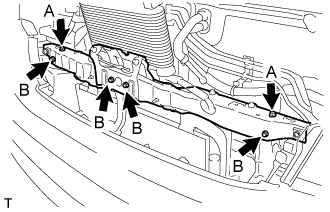
Install the upper radiator support with the 6 bolts.
- Torque:
- bolt A
- 13 N*m { 127 kgf*cm, 9 ft.*lbf }
- bolt B
- 5.5 N*m { 56 kgf*cm, 49 in.*lbf }
-
Install the 2 screws.
-
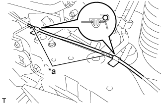
Text in Illustration *a Tape Align the ends of the tape and the ends of the clamps (vehicle outer side), connect the hood lock control cable to the clamps and install the hood lock control cable with the 2 clamps.
-
-
INSTALL HOOD LOCK ASSEMBLY
-
Connect the hood lock control cable.
-
Temporarily install the hood lock with the 3 bolts.
-
Check the hood position and adjust the hood lock position Click here.
-
Tighten the 3 bolts.
- Torque:
- 12 N*m { 122 kgf*cm, 9 ft.*lbf }
-
-
INSTALL RADIATOR RESERVE TANK ASSEMBLY
-
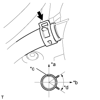
Text in Illustration *a Rear Side *b LH Side *c Blue Paint *d 30° Connect the No. 2 water by-pass hose as shown in the illustration.
-
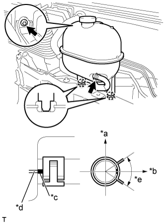
Text in Illustration *a Upper Side *b Front Side *c Pink Paint *d Protrusion *e 30° Insert the radiator reserve tank into the 2 grommets and install the radiator reserve tank with the bolt.
- Torque:
- 8.0 N*m { 82 kgf*cm, 71 in.*lbf }
-
Connect the water by-pass hose as shown in the illustration.
-
-
CONNECT UREA TANK FILLER PIPE ASSEMBLY
-
Connect the urea tank filler pipe support to the upper radiator support sub-assembly with the 2 bolts.
- Torque:
- 7.5 N*m { 76 kgf*cm, 66 in.*lbf }
-
-
INSTALL WINDSHIELD WASHER MOTOR AND PUMP ASSEMBLY
-
Connect the 2 connectors and 2 washer hoses.
-
Attach the hose clamp.
-
Install the windshield washer motor and pump assembly with the 2 bolts.
- Torque:
- 4.9 N*m { 50 kgf*cm, 43 in.*lbf }
-
-
ADD WINDSHIELD WASHER FLUID
-
INSTALL NO. 1 AIR INLET DUCT
-
Install the No. 1 air inlet duct with the 2 bolts.
- Torque:
- 7.0 N*m { 71 kgf*cm, 62 in.*lbf }
-
Attach the 2 clips.
-
-
INSTALL NO. 2 AIR INLET DUCT
-
Install the No. 2 air inlet duct with the 3 clips.
-
-
INSTALL RADIATOR GRILLE
-
Attach the 8 claws to install the radiator grille.
-
Install the 4 clips and 2 screws.
-
-
ADD COOLANT
-
Firmly tighten the drain plugs.
-
Fill the radiator reserve tank assembly with engine coolant to the top of the inlet.
Standard capacity 13.9 liters (14.6 US qts, 12.2 Imp qts) Note
Do not substitute plain water for engine coolant.
Tech Tips
-
Use of improper coolants may damage the engine cooling system.
-
Use only TOYOTA Super Long Life Coolant (SLLC) or similar high quality ethylene glycol based non-silicate, non-amine, non-nitrite, and non-borate coolant with long-life hybrid organic acid technology (coolant with long-life hybrid organic acid technology consists of a combination of low phosphates and organic acids).
-
-
Loosen the bleeder plug of the water outlet sub-assembly.
-
When air is bled and the engine coolant drains out, firmly tighten the bleeder plug.
- Torque:
- 8.0 N*m { 82 kgf*cm, 71 in.*lbf }
-
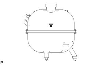
Add engine coolant up to the B line mark in the radiator reserve tank assembly and install the radiator cap sub-assembly.
-
Warm up the engine until the thermostat opens.
-
While the thermostat is open, circulate the engine coolant for several minutes.
Tech Tips
The thermostat open timing can be confirmed by pressing the No. 3 radiator hose by hand, and checking when the engine coolant starts to flow inside the hose.
-
-
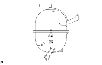
After the engine cools down, check that the engine coolant level is between the LOW and FULL line.
-
-
INSPECT FOR COOLANT LEAK
CAUTION:
Do not remove the radiator cap while the engine and radiator are still hot. Hot, pressurized engine coolant and steam may be released and cause serious burns.
-
Fill the radiator with coolant and attach a radiator cap tester to the radiator.
-
Warm up the engine.
-
Using a radiator cap tester, increase the pressure inside the radiator to 137 kPa (1.4 kgf/cm2, 19.9 psi), and check that the pressure does not drop.
Tech Tips
If the pressure drops, check the hoses, radiator and water pump for leaks. If no external leaks are found, check the heater core, cylinder block and cylinder head.
-