DYNAMIC RADAR CRUISE CONTROL SYSTEM, Diagnostic DTC:P057162
| DTC Code | DTC Name |
|---|---|
| P057162 | Brake Switch "A" Signal Compare Failure |
DESCRIPTION
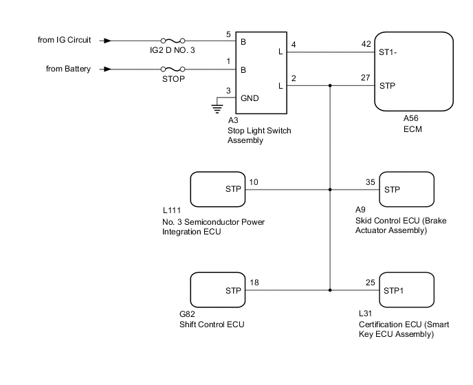
When the brake pedal is depressed, the stop light switch assembly outputs a signal to the ECM. When the ECM receives the signal, it cancels control of vehicle speed by the dynamic radar cruise control system. The fail-safe function operates to enable normal operation even if there is a malfunction in the stop light signal circuit. The cancellation condition occurs when voltage is applied to terminal STP. When the brake pedal is depressed, voltage is applied to terminal STP of the ECM through the STOP fuse and the stop light switch assembly, and the ECM turns the dynamic radar cruise control system off.
| DTC No. | Detection Item | DTC Detection Condition | Trouble Area |
|---|---|---|---|
| P057162 | Brake Switch "A" Signal Compare Failure | While the dynamic radar cruise control system is operating, voltage of STP terminal and that of ST1- terminal of ECM are less than 1 V for approximately 0.5 seconds or more. |
|
WIRING DIAGRAM
CAUTION / NOTICE / HINT
Note
-
Inspect the fuses for circuits related to this system before performing the following procedure.
-
After turning the engine switch off, waiting time may be required before disconnecting the cable from the negative (-) battery terminal. Therefore, make sure to read the disconnecting the cable from the negative (-) battery terminal notices before proceeding with work.
PROCEDURE
-
CHECK HARNESS AND CONNECTOR (STOP LIGHT SWITCH ASSEMBLY - BATTERY AND BODY GROUND)
-
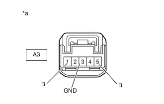
*a Front view of wire harness connector
(to Stop Light Switch Assembly)
Disconnect the A3 stop light switch assembly connector.
-
Measure the resistance according to the value(s) in the table below.
Standard Resistance Tester Connection Condition Specified Condition A3-3 (GND) - Body ground Always Below 1 Ω -
Measure the voltage according to the value(s) in the table below.
Standard Voltage Tester Connection Condition Specified Condition A3-1 (B) - Body ground Always 11 to 15.5 V A3-5 (B) - Body ground Engine switch on (IG) 11 to 14 V A3-5 (B) - Body ground Engine switch off Below 1 V -
Connect the A3 stop light switch assembly connector.
Result Proceed to OK NG
NG 
REPAIR OR REPLACE HARNESS OR CONNECTOR (STOP LIGHT SWITCH ASSEMBLY - BATTERY AND BODY GROUND)
OK 
-
-
INSPECT STOP LIGHT SWITCH ASSEMBLY
-
Inspect the stop light switch assembly.
Result Proceed to OK NG
NG
REPLACE STOP LIGHT SWITCH ASSEMBLY Click here
OK
-
-
CHECK HARNESS AND CONNECTOR (ECM - STOP LIGHT SWITCH ASSEMBLY)
-
Disconnect the cable from the negative (-) battery terminal.
-
Disconnect the A56 ECM connector.
-
Disconnect the A3 stop light switch assembly connector.
-
Disconnect the A9 skid control ECU (brake actuator assembly) connector.
-
Disconnect the G82 shift control ECU connector.
-
Disconnect the L111 No. 3 semiconductor power integration ECU connector.
-
Disconnect the L31 certification ECU (smart key ECU assembly) connector.
-
Measure the resistance according to the value(s) in the table below.
Standard Resistance Tester Connection Condition Specified Condition A56-42 (ST1-) - A3-4 (L) Always Below 1 Ω A56-27 (STP) - A3-2 (L) Always Below 1 Ω A56-42 (ST1-) or A3-4 (L) - Body ground Always 10 kΩ or higher A56-27 (STP) or A3-2 (L) - Body ground Always 10 kΩ or higher -
Connect the L31 certification ECU (smart key ECU assembly) connector.
-
Connect the L111 No. 3 semiconductor power integration ECU connector.
-
Connect the G82 shift control ECU connector.
-
Connect the A9 skid control ECU (brake actuator assembly) connector.
-
Connect the A3 stop light switch assembly connector.
-
Connect the A56 ECM connector.
-
Connect the cable from the negative (-) battery terminal.
Result Proceed to OK NG
OK
REPLACE ECM Click here
NG
REPAIR OR REPLACE HARNESS OR CONNECTOR (ECM - STOP LIGHT SWITCH ASSEMBLY)
-