ГЕНЕРАТОР (изготовитель – BOSCH) ПРОВЕРКА
-
INSPECT GENERATOR ROTOR ASSEMBLY
-
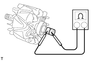
Check the rotor for an open circuit.
-
Measure the resistance between the slip rings.
Standard resistance 1.8 to 2.8 Ωat 20°C (68°F) If the result is not as specified, replace the rotor assembly.
-
-
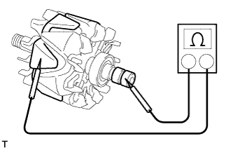
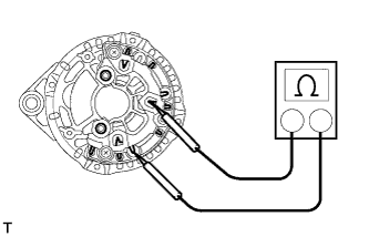
Check if the rotor is grounded.
-
Measure the resistance between the slip ring and rotor.
Standard resistance 10 kΩ or higher If the result is not as specified, replace the rotor assembly.
-
-
Check that the slip rings are not rough or scored.
If rough or scored, replace the rotor assembly.
-

Using a vernier caliper, measure the slip ring diameter.
Standard diameter 15.3 to 15.5 mm (0.602 to 0.610 in.) Minimum diameter 14.9 mm (0.587 in.) If the diameter is less than the minimum, replace the rotor assembly.
-
-
INSPECT GENERATOR STATOR SUB-ASSEMBLY WITH RECTIFIER

Tech Tips
For terminal positions of the stator generator, refer to the illustration below.
-
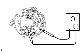
Inspect the positive (+) rectifier.
Tech Tips
Inspect the positive terminal after pulling it up.
-
Using an ohmmeter, connect one tester probe to the positive (+) terminal and the other to each rectifier terminal.
-
Reverse the polarity of the tester probes and repeat the step above.
-
Check that one shows a resistance of below 1 Ω and the other shows a resistance of 10 kΩ or higher.
If the result is not as specified, replace the generator stator sub-assembly with rectifier.
-
-
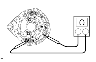
Inspect the negative (-) rectifier.
-
Using an ohmmeter, connect one tester probe to each negative (-) terminal and the other to each rectifier terminal.
-
Reverse the polarity of the tester probes and repeat the step above.
-
Check that one shows a resistance of below 1 Ω and the other shows a resistance of 10 kΩ or higher.
If the result is not as specified, replace the generator stator sub-assembly with rectifier.
-
-
Inspect the stator coil for an open circuit.
-
Measure the resistance between the rectifier terminals.
Standard resistance Below 1 Ω If the result is not as specified, replace the generator stator sub-assembly with rectifier.
-
-
-
INSPECT BRUSH
-
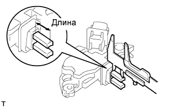
Using a vernier caliper, measure the exposed brush length.
Standard exposed length on new brush 13.2 mm (0.520 in.) Minimum exposed length 6.0 mm (0.236 in.) If the exposed length is less than the minimum, replace the generator regulator sub-assembly with brush.
-