POWER MIRROR CONTROL SYSTEM Front Passenger Side Power Mirror cannot be Adjusted with Power Mirror Switch
| DTC Code | DTC Name |
|---|---|
| Front Passenger Side Power Mirror cannot be Adjusted with Power Mirror Switch |
SYSTEM DESCRIPTION
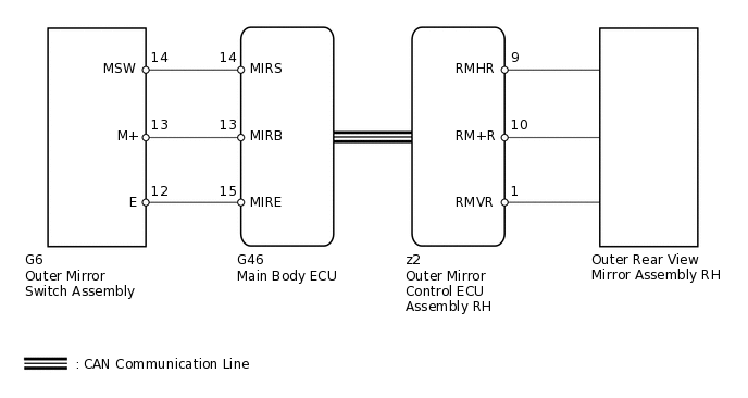
When the mirror adjust switch is operated, the main body ECU (multiplex network body ECU) detects the switch operation and sends the mirror adjust switch signal to the outer mirror control ECU assembly RH via CAN communication. Upon receiving the signal, the outer mirror control ECU assembly RH operates the vertical and horizontal mirror motors, which are built into the outer rear view mirror assembly RH, to adjust the mirror surface position.
WIRING DIAGRAM
PROCEDURE
CHECK CAN COMMUNICATION SYSTEM
Check if a CAN communication DTC is output.
Result
Result
Proceed to
DTC is not output
A
DTC is output
B
READ VALUE USING INTELLIGENT TESTER (OUTER MIRROR SWITCH)
Using the intelligent tester, read the Data List.
Body Electrical > Main Body > Data List
Tester Display
Measurement Item
Range
Normal Condition
Diagnostic Note
Mirror Selection SW (R)
Mirror select switch signal for RH mirror
ON or OFF
ON: Mirror select switch in R position
OFF: Mirror select switch off or in L position
-
Mirror Position SW (R)
Mirror adjust switch signal (Right)
ON or OFF
ON: Mirror adjust switch pressed right
OFF: Mirror adjust switch not pressed right
Check with the mirror select switch in the R position
Mirror Position SW (L)
Mirror adjust switch signal (Left)
ON or OFF
ON: Mirror adjust switch pressed left
OFF: Mirror adjust switch not pressed left
Check with the mirror select switch in the R position
Mirror Position SW (Up)
Mirror adjust switch signal (Up)
ON or OFF
ON: Mirror adjust switch pressed up
OFF: Mirror adjust switch not pressed up
Check with the mirror select switch in the R position
Mirror Position SW (Dwn)
Mirror adjust switch signal (Down)
ON or OFF
ON: Mirror adjust switch pressed down
OFF: Mirror adjust switch not pressed down
Check with the mirror select switch in the R position
OK
On intelligent tester screen, each item changes between ON and OFF according to above chart.
Result
Result
OK
NG
NG INSPECT OUTER MIRROR SWITCH ASSEMBLYClick here
PERFORM ACTIVE TEST USING INTELLIGENT TESTER (MIRROR CONTROL FUNCTION)
Select the Active Test, use the intelligent tester to generate a control command, and then check the mirror control function.
Body Electrical > Mirror R > Active Test
Tester Display
Measurement Item
Control Range
Diagnostic Note
Mirror Up/Down
Mirror vertical operation
Up / Down
-
Mirror Right/Left
Mirror horizontal operation
Right / Left
-
OK
Mirror operates normally.
Result
Result
OK
NG
INSPECT OUTER REAR VIEW MIRROR ASSEMBLY RH
-
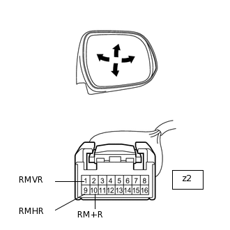
Remove the outer rear view mirror assembly RH.
Apply battery voltage and check the operation of the outer rear view mirror assembly RH.
OK
Measurement Condition
Specified Condition
Battery positive (+) → Terminal z2-1 (RMVR)
Battery negative (-) → Terminal z2-10 (RM+R)
Turns upward
Battery negative (-) → Terminal z2-1 (RMVR)
Battery positive (+) → Terminal z2-10 (RM+R)
Turns downward
Battery positive (+) → Terminal z2-9 (RMHR)
Battery negative (-) → Terminal z2-10 (RM+R)
Turns left
Battery negative (-) → Terminal z2-9 (RMHR)
Battery positive (+) → Terminal z2-10 (RM+R)
Turns right
Result
Result
OK
NG
-
INSPECT OUTER MIRROR SWITCH ASSEMBLY
-
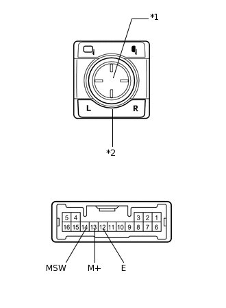
*1
Mirror Adjust Switch
*2
Mirror Select Switch
Remove the outer mirror switch assembly.
Measure the resistance according to the value(s) in the table below.
Standard Resistance
Tester Connection
Switch Condition
Specified Condition
13 (M+) - 12 (E)
Mirror select switch R
Mirror adjust switch pressed up
90 to 110 Ω
Mirror select switch R
Mirror adjust switch pressed down
437 to 503 Ω
Mirror select switch R
Mirror adjust switch pressed left
744 to 856 Ω
Mirror select switch R
Mirror adjust switch pressed right
225 to 275 Ω
14 (MSW) - 12 (E)
Mirror select switch R
Below 10 Ω
Mirror select switch off
10 kΩ or higher
Result
Result
OK
NG
-
CHECK HARNESS AND CONNECTOR (MAIN BODY ECU - OUTER MIRROR SWITCH)
Disconnect the G46 ECU connector.
Disconnect the G6 switch connector.
Measure the resistance according to the value(s) in the table below.
Standard Resistance
Tester Connection
Condition
Specified Condition
G46-15 (MIRE) - G6-12 (E)
Always
Below 1 Ω
G46-13 (MIRB) - G6-13 (M+)
Always
Below 1 Ω
G46-14 (MIRS) - G6-14 (MSW)
Always
Below 1 Ω
G46-15 (MIRE) - Body ground
Always
10 kΩ or higher
G46-13 (MIRB) - Body ground
Always
10 kΩ or higher
G46-14 (MIRS) - Body ground
Always
10 kΩ or higher
Result
Result
OK
NG
NG REPAIR OR REPLACE HARNESS OR CONNECTOR