BRAKE BOOSTER PUMP(for RHD) INSTALLATION

PROCEDURE
-
INSTALL BRAKE BOOSTER PUMP ASSEMBLY
-
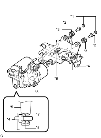
Text in Illustration *1 Nut *2 Brake Actuator Case Collar *3 Brake Traction Actuator Bracket Bushing *4 Brake Actuator Bracket Assembly *5 Brake Booster Pump Assembly *6 Brake Actuator Bracket Cushion *7 Brake Booster Pump Collar *8 Brake Booster Pump Bushing Install the brake booster pump assembly, 2 brake traction actuator bracket bushings and 2 brake actuator case collars to the brake actuator bracket assembly with the 2 nuts.
- Torque:
- 5.4 N*m { 55 kgf*cm, 48 in.*lbf }
Note
-
Do not drop the brake booster pump assembly when carrying it.
-
Do not carry the brake booster pump assembly by the connector.
-
Confirm that the 2 brake actuator bracket cushions are on the brake actuator bracket assembly, and each brake booster pump bushing and brake booster pump collar are on the brake booster pump assembly when installing the brake booster pump assembly to the brake actuator bracket assembly.
-
Do not remove the hole plugs before installing a new brake booster pump assembly because the brake booster pump assembly is filled with brake fluid.
-
-
INSTALL BRAKE BOOSTER PUMP ASSEMBLY WITH BRACKET
-
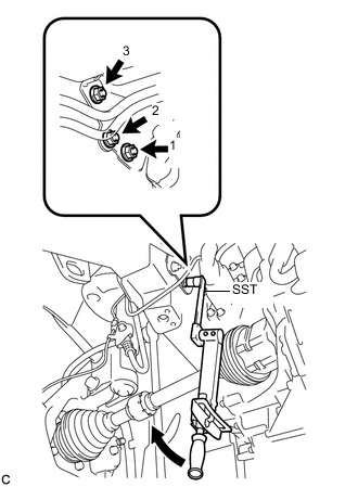
Using SST, install the brake booster pump assembly with bracket with the 3 nuts.
- SST
- 09961-00950
- Torque:
- without SST
- 19 N*m { 194 kgf*cm, 14 ft.*lbf }
- with SST
- 12 N*m { 121 kgf*cm, 9 ft.*lbf }
Note
-
Use a torque wrench with a fulcrum length of 250 mm (9.84 in.).
-
Tighten the 3 nuts in the order shown in the illustration.
-
Do not damage the fuel line, the brake lines or wire harness.
-
Use the formula to calculate special torque values for situations where SST is combined with a torque wrench Click here.
-
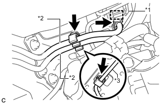
Text in Illustration *1 Wire Harness Clamp *2 Fuel Line *3 Front No. 4 Brake Tube Install the wire harness clamp and 2 fuel lines to the brake actuator bracket assembly.
Note
Do not kink or damage the fuel lines.
-
Engage the clamp to install the front No. 4 brake tube to the brake actuator bracket assembly.
Note
Do not kink or damage the brake line.
-
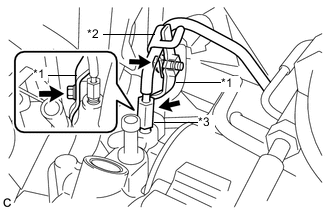
Text in Illustration *1 No. 1 Brake Tube Clamp Bracket *2 No. 6 Brake Tube Clamp *3 No. 1 Front Brake Tube Install the No. 1 brake tube clamp bracket to the brake booster pump assembly with the bolt.
- Torque:
- 7.0 N*m { 71 kgf*cm, 62 in.*lbf }
-
Using a union nut wrench, connect the front No. 1 brake tube to the brake booster pump assembly.
- Torque:
- 15 N*m { 155 kgf*cm, 11 ft.*lbf }
Note
Use the formula to calculate special torque values for situations where the union nut wrench is combined with a torque wrench Click here.
-
Install the No. 6 brake tube clamp to the No. 1 brake tube clamp bracket with the bolt.
- Torque:
- 7.0 N*m { 71 kgf*cm, 62 in.*lbf }
-
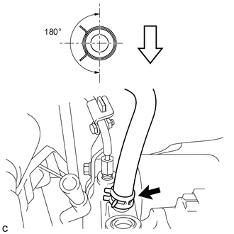
Connect the No. 1 brake actuator hose to the brake booster pump assembly.
Text in Illustration 
Front of Vehicle Note
-
Make sure to match the identification mark on the hose with the brake booster pump rib.
-
Install the clip within the range as shown in the illustration.
-
-
Install the wire harness clamp.
-
Connect the 2 connectors.
-
-
INSTALL NO. 5 BRAKE ACTUATOR BRACKET
-
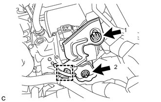
Install the No. 5 brake actuator bracket with the 2 nuts.
- Torque:
- 8.5 N*m { 87 kgf*cm, 75 in.*lbf }
Note
Tighten the 2 nuts in the order shown in the illustration.
-
Install the wire harness clamp.
-
-
INSTALL FRONT SUSPENSION CROSSMEMBER SUB-ASSEMBLY
-
SEPARATE BRAKE MASTER CYLINDER RESERVOIR WITH BRACKET
-
BLEED NO. 1 BRAKE ACTUATOR TUBE
-
INSTALL BRAKE MASTER CYLINDER RESERVOIR WITH BRACKET
-
FILL RESERVOIR WITH BRAKE FLUID
-
CONNECT CABLE TO NEGATIVE AUXILIARY BATTERY TERMINAL
-
BLEED BRAKE SYSTEM
-
INSTALL OUTER COWL TOP PANEL SUB-ASSEMBLY
-
INSTALL COWL BODY MOUNTING REINFORCEMENT RH
-
INSTALL WINDSHIELD WIPER MOTOR AND LINK ASSEMBLY