LIGHTING SYSTEM TERMINALS OF ECU
-
CHECK INSTRUMENT PANEL JUNCTION BLOCK ASSEMBLY AND MAIN BODY ECU (MULTIPLEX NETWORK BODY ECU)
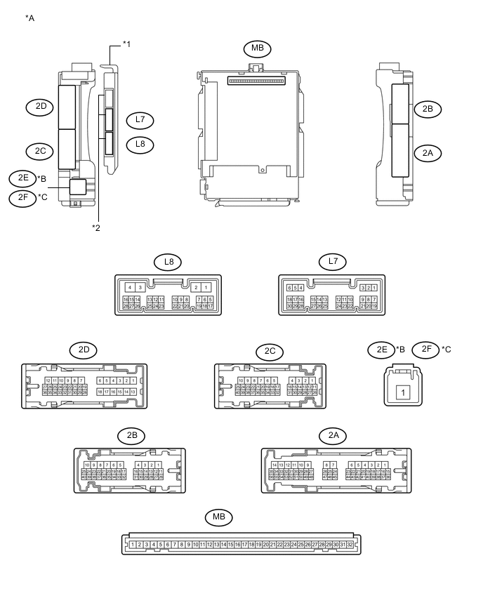
Text in Illustration *A Main Body ECU (Multiplex Network Body ECU) with 3 connectors *B for LHD *C for RHD - - *1 Main Body ECU (Multiplex Network Body ECU) *2 3 connectors 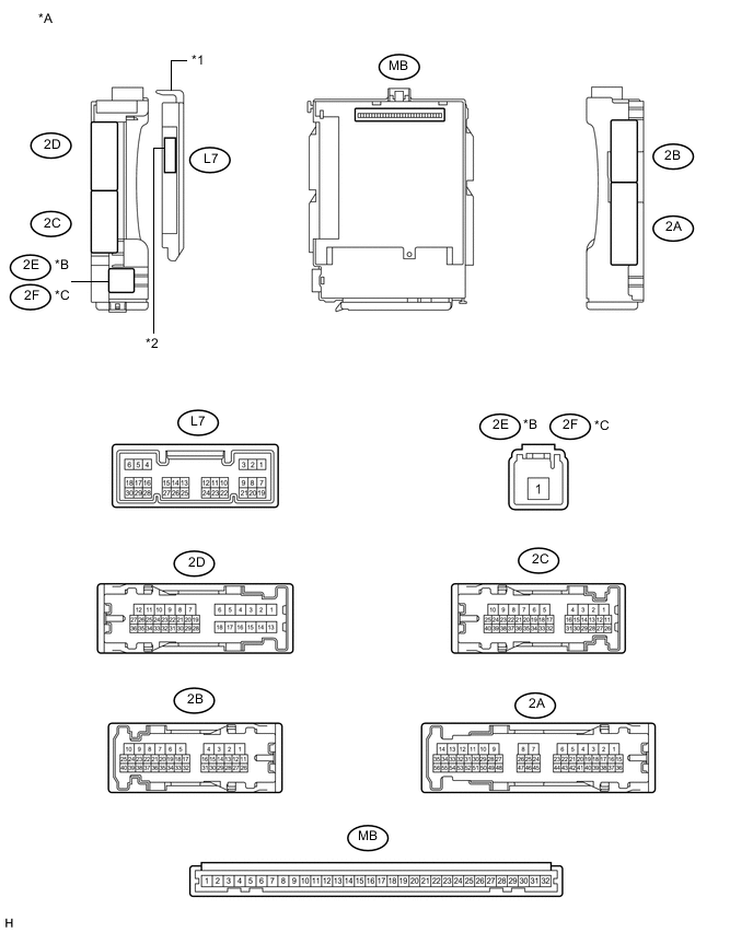
Text in Illustration *A Main Body ECU (Multiplex Network Body ECU) with 1 connectors *B for LHD *C for RHD - - *1 Main Body ECU (Multiplex Network Body ECU) *2 1 connector
-
Disconnect the 2A, 2B, 2C, 2E, 2F and L8 instrument panel junction block assembly and main body ECU (multiplex network body ECU) connectors.
-
Measure the voltage according to the value(s) in the table below.
Terminal No. (Symbol) Wiring Color Terminal Description Condition Specified Condition 2A-43 - Body ground G - Body ground ACC power supply Power switch on (ACC) 11 to 14 V Power switch off Below 1 V 2B-25 - Body ground B - Body ground IG power supply Power switch on (IG) 11 to 14 V Power switch off Below 1 V 2C-18 (BECU) - Body ground Y - Body ground Auxiliary battery power supply Power switch off 11 to 14 V 2E-1*1 - Body ground W - Body ground Auxiliary battery power supply Power switch off 11 to 14 V 2F-1*2 - Body ground W - Body ground Auxiliary battery power supply Power switch off 11 to 14 V If the result is not as specified, there may be a malfunction in the wire harness.
-
Measure the resistance according to the value(s) in the table below.
Terminal No. (Symbol) Wiring Color Terminal Description Condition Specified Condition 2B-6 (GND1) - Body ground W-B - Body ground Ground Always Below 1 Ω L8-3 (GND2)*5 - Body ground W-B - Body ground Ground Always Below 1 Ω If the result is not as specified, there may be a malfunction in the wire harness.
-
Reconnect the 2A, 2B, 2C, 2E, 2F and L8 instrument panel junction block assembly and main body ECU (multiplex network body ECU) connectors.
-
Measure the voltage or check for pulses according to the value(s) in the table below.
Terminal No. (Symbol) Wiring Color Terminal Description Condition Specified Condition 2B-26 (RFGO) - Body ground Y - Body ground Rear fog light drive output Light control switch in tail position, rear fog light switch on Below 1 V Light control switch in tail position, rear fog light switch off 11 to 14 V 2C-8*3 - Body ground LG - Body ground Front fog lights drive output Light control switch in tail position, front fog light switch on 11 to 14 V Light control switch in tail position, front fog light switch off Below 1 V 2C-20 (PKB) - Body ground R - Body ground Parking brake switch input Parking brake switch on Below 1 V Parking brake switch off 11 to 14 V 2C-22 (DIM) - Body ground Y - Body ground High beam headlights drive output Dimmer switch in high or high flash position Below 1 V Dimmer switch in low position 11 to 14 V 2C-32 (HRLY) - Body ground G - Body ground Headlight relay drive output Light control switch in head position Below 1 V Light control switch not in head position 11 to 14 V L7-1 (RFOG) - Body ground W - Body ground Rear fog light switch input Rear fog light switch on Below 1 V Rear fog light switch off Pulse generation L7-8 (HF) - Body ground R - Body ground Dimmer switch high flash position signal input Dimmer switch in high flash position Below 1 V Dimmer switch not in high flash position Pulse generation L7-15 (DRLE) - Body ground Y - Body ground Daytime running light system drive output Daytime running light system operating Below 1 V Daytime running light system not operating 11 to 14 V L7-20 (CLTB) - L7-22 (CLTE)*4 R - B Automatic light control sensor power supply output Power switch off Below 1 V Power switch on (IG) and light control switch in AUTO position 11 to 14 V L7-21 (CLTS) - Body ground W - Body ground Automatic light control sensor signal input Power switch off Below 1 V Automatic light control system operates Pulse generation
(See waveform 1)
L7-27 (FFOG)*3 - Body ground SB - Body ground Front fog light switch input Front fog light switch on Below 1 V Front fog light switch off Pulse generation L7-28 (A)*4 - Body ground G - Body ground Light control switch AUTO position signal input Light control switch in AUTO position Below 1 V Light control switch not in AUTO position Pulse generation L7-29 (HEAD) - Body ground P - Body ground Light control switch head position input Light control switch in head position Below 1 V Light control switch not in head position Pulse generation L7-30 (TAIL) - Body ground Y - Body ground Light control switch tail position signal input Light control switch in tail or head position Below 1 V Light control switch in neither tail nor head position 11 to 14 V L8-5 (RLEW)*6 - Body ground L - Body ground Light control ECU RH signal input Power switch on (IG) and light control switch off 11 to 14 V Power switch on (IG) and light control switch in head position Pulse generation L8-21 (LLEW)*6 - Body ground B - Body ground Light control ECU LH signal input Power switch on (IG) and light control switch off 11 to 14 V Power switch on (IG) and light control switch in head position Pulse generation L8-17 (AHBI)*7 - Body ground R - Body ground Auto high beam switch signal input Auto high beam switch on Below 1 V Auto high beam switch off 11 to 14 V If the result is not as specified, the main body ECU (multiplex network body ECU) or instrument panel junction block assembly may have a malfunction.
-
*1: for LHD
-
*2: for RHD
-
*3: w/ Front Fog Light
-
*4: w/ Automatic Light Control
-
*5: Main Body ECU (Multiplex Network Body ECU) with 3 connectors
-
*6: for LED Headlight
-
*7: w/ Automatic High Beam System
-
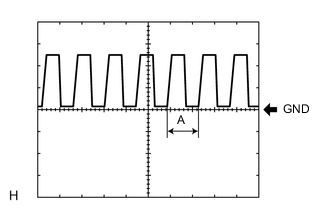
Waveform 1
Item Content Tool setting 5 V/DIV., 5 ms./DIV. Tech Tips
If the ambient light becomes brighter, width A becomes narrower.
-
-
-
CHECK HEADLIGHT LEVELING ECU ASSEMBLY

-
Disconnect the A48 headlight leveling ECU assembly connector.
-
Measure the voltage and resistance according to the value(s) in the table below.
Standard Voltage Terminal No. (Symbol) Wiring Color Terminal Description Condition Specified Condition A48-1 (IG) - Body ground LG - Body ground IG power supply Power switch off Below 1 V Power switch on (IG) 11 to 14 V Standard Resistance Terminal No. (Symbol) Wiring Color Terminal Description Condition Specified Condition A48-9 (E1) - Body ground W-B - Body ground Ground Always Below 1 Ω If the result is not as specified, there may be a malfunction on the wire harness side.
-
Reconnect the A48 headlight leveling ECU assembly connector.
-
Measure the resistance and voltage according to the value(s) in the table below.
Standard Resistance Terminal No. (Symbol) Wiring Color Terminal Description Condition Specified Condition A48-21 (SGR) - Body ground Y - Body ground Rear height control sensor ground Always Below 1 Ω A48-23 (RH-) - Body ground BR - Body ground Leveling motor RH ground Always Below 1 Ω A48-24 (LH-) - Body ground LG - Body ground Leveling motor LH ground Always Below 1 Ω Standard Voltage Terminal No. (Symbol) Wiring Color Terminal Description Condition Specified Condition A48-3 (HDLP) - Body ground V - Body ground Low beam headlight signal input Low beam headlights on Below 1.5 V Low beam headlights off Above 5 V A48-5 (INIT) - Body ground B - Body ground Initialization signal input Terminals LVL and GND of DLC3 connected Below 1 V Terminals LVL and GND of DLC3 not connected Approximately 5 V A48-6 (WNG) - Body ground L - Body ground Warning light drive output Warning light on Below 1 V Warning light off 11 to 14 V A48-10 (RH+) - Body ground W - Body ground Leveling motor RH power supply Power switch off Below 1 V Power switch on (IG) 11 to 14 V A48-11 (LH+) - Body ground R - Body ground Leveling motor LH power supply Power switch off Below 1 V Power switch on (IG) 11 to 14 V A48-12 (SBR) - Body ground P - Body ground Rear height control sensor power supply Power switch off Below 1 V Power switch on (IG) 4.75 to 5.25 V A48-16 (SPDR) - Body ground V - Body ground Vehicle speed signal input Vehicle is driven at approximately 20 km/h (12 mph) Pulse generation
(See waveform 1)
A48-17 (RHT) - Body ground B - Body ground Leveling motor RH operation signal input With low beam headlights on, vehicle height not changed Below 1 V With low beam headlights on, change vehicle height and keep for more than 3 seconds 1.0 to 14.4 V A48-18 (LHT) - Body ground G - Body ground Leveling motor LH operation signal input With low beam headlights on, vehicle height not changed Below 1 V With low beam headlights on, change vehicle height and keep for more than 3 seconds 1.0 to 14.4 V A48-19 (SHRL) - Body ground SB - Body ground Rear height control sensor signal input Power switch off Below 1 V Power switch on (IG) 0.5 to 4.5 V If the result is not as specified, the headlight leveling ECU assembly may have a malfunction.
-
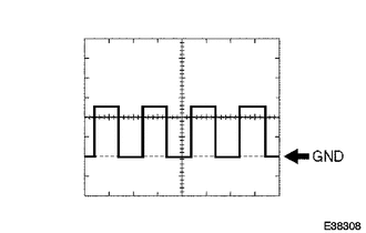
Waveform 1
Item Content Tool setting 2 V/DIV., 2 ms./DIV.
-
-
-
CHECK POWER MANAGEMENT CONTROL ECU
-
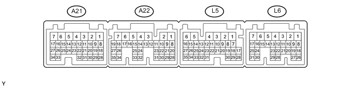
Disconnect the A21 power management control ECU connector.
-
Measure the voltage and resistance according to the value(s) in the table below.
Standard Voltage Terminal No. (Symbol) Wiring Color Terminal Description Condition Specified Condition A21-15 (BL) - Body ground R - Body ground Back up light Power switch on (IG), shift lever in R 11 to 14 V If the result is not as specified, there may be a malfunction on the wire harness side.
-