FUEL SYSTEM SYSTEM DIAGRAM
-
FUEL FLOW DIAGRAM
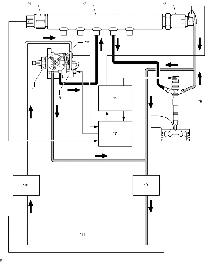
*1 Fuel Pressure Sensor *2 Common Rail Assembly *3 Pressure Discharge Valve *4 Fuel Supply Pump Assembly *5 Suction Control Valve *6 Injector Driver *7 ECM *8 Injector Assembly *9 Fuel Cooler *10 Fuel Filter Assembly *11 Fuel Tank Assembly *12 Fuel Temperature Sensor 
High Pressure Fuel Line 
Return Fuel Line 
Suction Fuel Line - - -
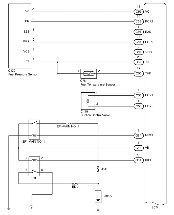
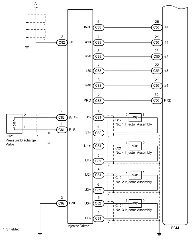
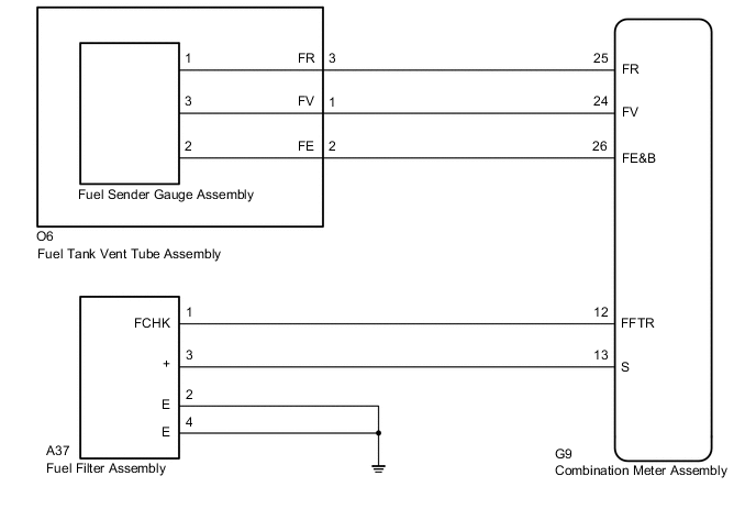
FUEL SYSTEM WIRING DIAGRAM
-
By storing fuel at a high pressure, the common rail system provides the pressure necessary for fuel injection.
-