LIN COMMUNICATION SYSTEM TERMINALS OF ECU
CHECK MAIN BODY ECU (INSTRUMENT PANEL JUNCTION BLOCK ASSEMBLY)
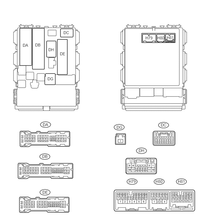
Disconnect the H80, DB and DE ECU connectors.
Measure the resistance and voltage according to the value(s) in the table below.
Terminal No. (Symbol)
Wiring Color
Terminal Description
Condition
Specified Condition
H80-4 (GND2) - Body ground
W-B - Body ground
Ground
Always
Below 1 Ω
DE-28 (GND1) - Body ground
W-B - Body ground
Ground
Always
Below 1 Ω
DH-12 (BECU) - Body ground
B - Body ground
Battery power supply
Always
11 to 14 V
If the result is not as specified, there may be a malfunction on the wire harness side.
CHECK POWER WINDOW REGULATOR MASTER SWITCH ASSEMBLY

Table 1. Text in Illustration *1
for LHD
*2
for RHD
Disconnect the K5*1 or J5*2 master switch connector.
*1: for LHD
*2: for RHD
Measure the resistance and voltage according to the value(s) in the table below.
Table 2. for LHD Terminal No. (Symbol)
Wiring Color
Terminal Description
Condition
Specified Condition
K5-11 (B) - Body ground
R - Body ground
Battery power supply
Always
11 to 14 V
K5-12 (GND) - Body ground
W-B - Body ground
Ground
Always
Below 1 Ω
Table 3. for RHD Terminal No. (Symbol)
Wiring Color
Terminal Description
Condition
Specified Condition
J5-11 (B) - Body ground
R - Body ground
Battery power supply
Always
11 to 14 V
J5-12 (GND) - Body ground
W-B - Body ground
Ground
Always
Below 1 Ω
If the result is not as specified, there may be a malfunction on the wire harness side.
CHECK FRONT DOOR WINDOW REGULATOR ASSEMBLY LH

Table 4. Text in Illustration *1
for LHD
*2
for RHD
Disconnect the K8*1 or K10*2 regulator connector.
*1: for LHD
*2: for RHD
Measure the resistance and voltage according to the value(s) in the table below.
Table 5. for LHD Terminal No. (Symbol)
Wiring Color
Terminal Description
Condition
Specified Condition
K8-2 (B) - Body ground
L - Body ground
Battery power supply
Always
11 to 14 V
K8-1 (GND) - Body ground
W-B - Body ground
Ground
Always
Below 1 Ω
Table 6. for RHD Terminal No. (Symbol)
Wiring Color
Terminal Description
Condition
Specified Condition
K10-2 (B) - Body ground
G - Body ground
Battery power supply
Always
11 to 14 V
K10-1 (GND) - Body ground
W-B - Body ground
Ground
Always
Below 1 Ω
If the result is not as specified, there may be a malfunction on the wire harness side.
CHECK FRONT DOOR WINDOW REGULATOR ASSEMBLY RH

Table 7. Text in Illustration *1
for LHD
*2
for RHD
Disconnect the J8*1 or J6*2 regulator connector.
*1: for LHD
*2: for RHD
Measure the resistance and voltage according to the value(s) in the table below.
Table 8. for LHD Terminal No. (Symbol)
Wiring Color
Terminal Description
Condition
Specified Condition
J8-2 (B) - Body ground
G - Body ground
Battery power supply
Always
11 to 14 V
J8-1 (GND) - Body ground
W-B - Body ground
Ground
Always
Below 1 Ω
Table 9. for RHD Terminal No. (Symbol)
Wiring Color
Terminal Description
Condition
Specified Condition
J6-2 (B) - Body ground
L - Body ground
Battery power supply
Always
11 to 14 V
J6-1 (GND) - Body ground
W-B - Body ground
Ground
Always
Below 1 Ω
If the result is not as specified, there may be a malfunction on the wire harness side.
CHECK REAR DOOR WINDOW REGULATOR ASSEMBLY LH (w/ Rear Door Power Window)

Disconnect the M3 regulator connector.
Measure the resistance and voltage according to the value(s) in the table below.
Terminal No. (Symbol)
Wiring Color
Terminal Description
Condition
Specified Condition
M3-2 (B) - Body ground
BR - Body ground
Battery power supply
Always
11 to 14 V
M3-1 (GND) - Body ground
W-B - Body ground
Ground
Always
Below 1 Ω
If the result is not as specified, there may be a malfunction on the wire harness side.
CHECK REAR DOOR WINDOW REGULATOR ASSEMBLY RH (w/ Rear Door Power Window)

Disconnect the L3 regulator connector.
Measure the resistance and voltage according to the value(s) in the table below.
Terminal No. (Symbol)
Wiring Color
Terminal Description
Condition
Specified Condition
L3-2 (B) - Body ground
L - Body ground
Battery power supply
Always
11 to 14 V
L3-1 (GND) - Body ground
W-B - Body ground
Ground
Always
Below 1 Ω
If the result is not as specified, there may be a malfunction on the wire harness side.
CHECK SLIDING ROOF DRIVE GEAR SUB-ASSEMBLY (w/ Roof Sunshade System)

Disconnect the z3 drive gear connector.
Measure the resistance and voltage according to the value(s) in the table below.
Terminal No. (Symbol)
Wiring Color
Terminal Description
Condition
Specified Condition
z3-1 - Body ground
W-R - Body ground
Battery power supply
Always
11 to 14 V
z3-2 - Body ground
W-B - Body ground
Ground
Always
Below 1 Ω
If the result is not as specified, there may be a malfunction on the wire harness side.
CHECK CERTIFICATION ECU (w/ Entry and Start System)
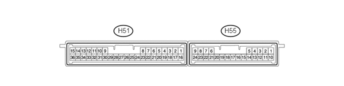
Disconnect the H51 ECU connector.
Measure the resistance and voltage according to the value(s) in the table below.
Terminal No. (Symbol)
Wiring Color
Terminal Description
Condition
Specified Condition
H51-1 (+B) - Body ground
W - Body ground
Battery power supply
Always
11 to 14 V
H51-15 (E) - Body ground
W-B - Body ground
Ground
Always
Below 1 Ω
If the result is not as specified, there may be a malfunction on the wire harness side.
CHECK POWER MANAGEMENT CONTROL ECU (w/ Entry and Start System)
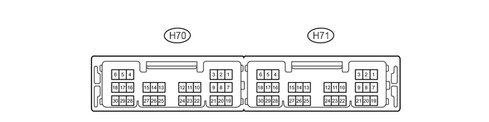
Disconnect the H71 ECU connector.
Measure the resistance and voltage according to the value(s) in the table below.
Terminal No. (Symbol)
Wiring Color
Terminal Description
Condition
Specified Condition
H71-1 (AM22) - Body ground
L - Body ground
Battery power supply
Always
11 to 14 V
H71-2 (AM21) - Body ground
B - Body ground
Battery power supply
Always
11 to 14 V
H71-6 (GND) - Body ground
W-B - Body ground
Ground
Always
Below 1 Ω
H71-5 (GND2) - Body ground
W-B - Body ground
Ground
Always
Below 1 Ω
CHECK ID CODE BOX (w/ Entry and Start System)
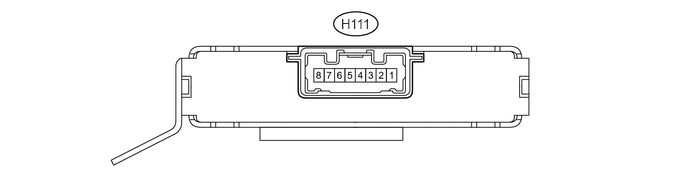
Disconnect the H111 box connector.
Measure the resistance and voltage according to the value(s) in the table below.
Terminal No. (Symbol)
Wiring Color
Terminal Description
Condition
Specified Condition
H111-1 (+B) - Body ground
W - Body ground
Battery power supply
Always
11 to 14 V
H111-8 (GND) - Body ground
BR - Body ground
Ground
Always
Below 1 Ω
If the result is not as specified, there may be a malfunction on the wire harness side.
CHECK STEERING LOCK ACTUATOR ASSEMBLY (w/ Entry and Start System)

Disconnect the H54 actuator connector.
Measure the resistance and voltage according to the value(s) in the table below.
Terminal No. (Symbol)
Wiring Color
Terminal Description
Condition
Specified Condition
H54-7 (B) - Body ground
L - Body ground
Battery power supply
Always
11 to 14 V
H54-1 (GND) - Body ground
W-B - Body ground
Ground
Always
Below 1 Ω
If the result is not as specified, there may be a malfunction on the wire harness side.
CHECK AIR CONDITIONING AMPLIFIER ASSEMBLY (for Automatic Air Conditioning System)
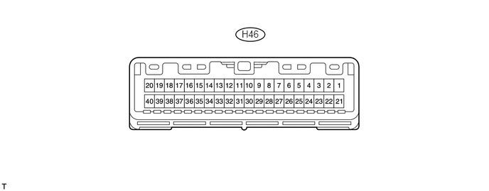
Disconnect the H46 amplifier connector.
Measure the resistance and voltage according to the value(s) in the table below.
Terminal No. (Symbol)
Wiring Color
Terminal Description
Condition
Specified Condition
H46-1 (IG+) - Body ground
Y - Body ground
IG power supply
Ignition switch off
Below 1 V
H46-1 (IG+) - Body ground
Y - Body ground
IG power supply
Ignition switch ON
11 to 14 V
H46-21 (B) - Body ground
W - Body ground
Battery power supply
Always
11 to 14 V
H46-14 (GND) - Body ground
W-B - Body ground
Ground
Always
Below 1 Ω
If the result is not as specified, there may be a malfunction on the wire harness side.
CHECK AIR CONDITIONING CONTROL ASSEMBLY (for Automatic Air Conditioning System)

Disconnect the H21 control connector.
Measure the resistance and voltage according to the value(s) in the table below.
Terminal No. (Symbol)
Wiring Color
Terminal Description
Condition
Specified Condition
H21-2 (IG+) - Body ground
R - Body ground
IG power supply
Ignition switch off
Below 1 V
H21-2 (IG+) - Body ground
R - Body ground
IG power supply
Ignition switch ON
11 to 14 V
H21-5 (GND) - Body ground
BR - Body ground
Ground
Always
Below 1 Ω
If the result is not as specified, there may be a malfunction on the wire harness side.
CHECK RAIN SENSOR (w/ Rain Sensor)

Disconnect the Q5 sensor connector.
Measure the voltage according to the value(s) in the table below.
Terminal No. (Symbol)
Wiring Color
Terminal Description
Condition
Specified Condition
Q5-3 (SIG) - Body ground
P - Body ground
IG power supply
Ignition switch off
Below 1 V
Q5-3 (SIG) - Body ground
P - Body ground
IG power supply
Ignition switch ON
11 to 14 V
Q5-2 (ES) - Body ground
LG - Body ground
Ground
Always
Below 1 V
If the result is not as specified, there may be a malfunction on the wire harness side.
CHECK WINDSHIELD WIPER RELAY ASSEMBLY (w/ Rain Sensor)
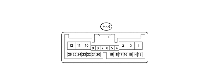
Disconnect the H56 relay connector.
Measure the voltage and resistance according to the value(s) in the table below.
Terminal No. (Symbol)
Wiring Color
Terminal Description
Condition
Specified Condition
H56-2 (IG) - Body ground
L - Body ground
IG power supply
Ignition switch off
Below 1 V
H56-2 (IG) - Body ground
L - Body ground
IG power supply
Ignition switch ON
11 to 14 V
H56-12 (E) - Body ground
BR - Body ground
Ground
Always
Below 1 Ω
If the result is not as specified, there may be a malfunction on the wire harness side.
CHECK DOUBLE LOCK DOOR CONTROL RELAY ASSEMBLY (w/ Double Locking System)

Disconnect the H50 relay connector.
Measure the voltage and resistance according to the value(s) in the table below.
Terminal No. (Symbol)
Wiring Color
Terminal Description
Condition
Specified Condition
H50-7 (CPUB) - Body ground
W - Body ground
Battery power supply
Always
11 to 14 V
H50-1 (+B) - Body ground
B - Body ground
Battery power supply
Always
11 to 14 V
H50-14 (GND) - Body ground
W-B - Body ground
Ground
Always
Below 1 Ω
If the result is not as specified, there may be a malfunction on the wire harness side.