ELECTRONIC CONTROLLED AUTOMATIC TRANSMISSION SYSTEM (for 1KD-FTV), Diagnostic DTC:P2769, P2770
| DTC Code | DTC Name |
|---|---|
| P2769 | Short in Torque Converter Clutch Solenoid Circuit (Shift Solenoid Valve SL) |
| P2770 | Open in Torque Converter Clutch Solenoid Circuit (Shift Solenoid Valve SL) |
DESCRIPTION
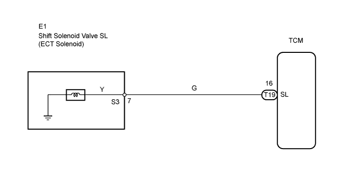
The shift solenoid valve SL is turned ON and OFF by signals from the TCM to control the hydraulic pressure acting on the lock-up relay valve, which then controls operation of the lock-up clutch.
| DTC No. | DTC Detection Condition | Trouble Area |
|---|---|---|
| P2769 | TCM detects short in shift solenoid valve SL circuit (once) when shift solenoid valve SL is operated (1 trip detection logic) |
|
| P2770 | TCM detects open in shift solenoid valve SL circuit (once) when shift solenoid valve SL is not operated (1 trip detection logic) |
|
Fail-safe function:
If the TCM detects a malfunction, it turns the shift solenoid valve SL OFF.
MONITOR DESCRIPTION
Torque converter lock-up is controlled by the TCM based on engine rpm, engine load, engine temperature, vehicle speed, transmission temperature, and shift position selection. The TCM determines the lock-up status of the torque converter by comparing the engine rpm (NE) to the input rpm (NC0). The TCM calculates the actual transmission gear by comparing the input rpm (NC0) to the output rpm (SP2). When conditions are appropriate, the TCM requests "lock-up" by applying control voltage to the shift solenoid valve SL. When the shift solenoid valve SL is opened, the shift solenoid valve SL applies pressure to the lock-up relay valve and locks the torque converter clutch. If the TCM detects an open or short in the shift solenoid valve SL circuit, the TCM interprets this as a fault in the shift solenoid valve SL or its circuit. The TCM will store a DTC.
WIRING DIAGRAM
INSPECTION PROCEDURE
PROCEDURE
-
INSPECT TRANSMISSION WIRE (SHIFT SOLENOID VALVE SL)
-
Disconnect the E1 wire connector.
-
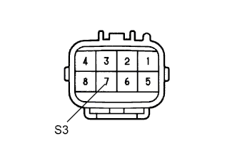
Measure the resistance of the transmission wire.
Standard resistance Tester Connection Condition Specified Condition 7 (S3) - Body ground 20°C (68°F) 11 to 15 Ω
NG 
INSPECT SHIFT SOLENOID VALVE SL Click here
OK 
-
-
CHECK WIRE HARNESS (SHIFT SOLENOID VALVE SL - TCM)
-
Disconnect the T19 TCM connector.
-
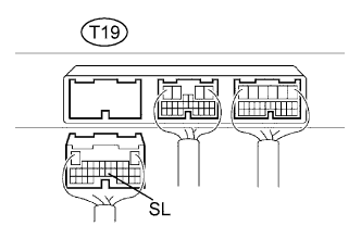
Measure the resistance of the wire harness side connector.
Standard resistance Tester Connection Condition Specified Condition T19-16 (SL) - Body ground 20°C (68°F) 11 to 15 Ω
NG 
REPAIR OR REPLACE HARNESS AND CONNECTOR
OK 
REPLACE TCM
-
-
INSPECT SHIFT SOLENOID VALVE SL
-
Remove the shift solenoid valve SL.
-
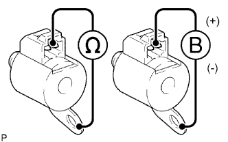
Measure the resistance between the solenoid valve terminal and solenoid valve body.
Standard resistance 11 to 15 Ωat 20°C (68°F) -
Connect the battery's positive (+) lead to the terminal of the solenoid connector, and the negative (-) lead to the solenoid body.
-
Check the operating noise of the solenoid valve.
OK Solenoid makes operating noise.
NG
REPLACE SHIFT SOLENOID VALVE SL
OK
REPLACE TRANSMISSION WIRE
-