STOP AND START SYSTEM, Diagnostic DTC:P0335
| DTC Code | DTC Name |
|---|---|
| P0335 | Engine Speed Sensor Circuit (NE Circuit) |
DESCRIPTION
The crank position sensor sends an engine speed signal (NE signal) to the ECM. The engine speed signal is then sent directly from the NEO terminal of the ECM to the engine stop and start ECU. Additionally, the ECM sends the engine speed to the engine stop and start ECU via CAN communication. The engine stop and start ECU compares the NE signal and engine speed received via CAN communication to check for errors in the NE signal.
If the NE signal is abnormal, the engine stop and start ECU will blink the stop and start cancel indicator light and stores DTC P0335.
DTC No. |
Detection Item |
DTC Detection Condition |
Trouble Area |
Warning Indicate |
Memory |
|---|---|---|---|---|---|
P0335 |
Engine Speed Sensor Circuit (NE Circuit) |
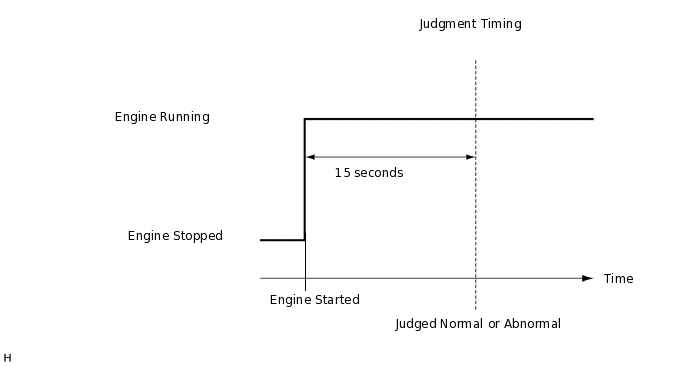
All of the following conditions are met for 10 seconds (2 trip detection logic):
Both of the following conditions are met for 2 seconds or more (1 trip detection logic):
|
|
Blinks |
DTC stored |
CONFIRMATION DRIVING PATTERN
DTCs for the stop and start system are not cleared automatically even if the malfunction has been repaired. After repairing the malfunction, be sure to clear the DTCs.
CONFIRMATION AFTER TROUBLESHOOTING
Tip:If the cable is disconnected from the negative (-) battery terminal, stop and start control is prohibited until refresh charge is completed. In this case, drive the vehicle approximately 5 to 40 minutes until refresh charge is completed and stop and start control operation is permitted.
Allow the engine to idle for 3 minutes after it is warmed up and check that the engine idle speed is within 50 rpm of the target idle speed.
Connect the GTS to the DLC3.
Turn the ignition switch to ON and turn the GTS on.
Clear the DTCs.
Powertrain > Stop and Start > Clear DTCs
Start the engine and wait for at least 15 seconds.
Check that DTCs are not output.
Powertrain > Stop and Start > Trouble Codes
STOP AND START SYSTEM OPERATION CHECK
Tip:If the cable is disconnected from the negative (-) battery terminal, stop and start control is prohibited until refresh charge is completed. In this case, drive the vehicle approximately 5 to 40 minutes until refresh charge is completed and stop and start control operation is permitted.
Start the engine and warm it up.
Turn the air conditioning system off.
Drive the vehicle at 7 km/h (4.3 mph) or more.
CAUTION:When performing Confirmation Driving Pattern, obey all speed limits and traffic laws.
Stop the vehicle, move the shift lever to neutral and release the clutch pedal. (for Manual Transaxle)
Depress the brake pedal and stop the vehicle. (for CVT)
Allow the engine to stop by stop and start control. (Keep the shift lever in D. (for CVT))
Depress the clutch pedal and start the engine. (for Manual Transaxle)
Release the brake pedal with the shift lever in D to start the engine. (for CVT)
WIRING DIAGRAM

CAUTION / NOTICE / HINT
Before replacing the engine stop and start ECU, read the number of starter operations and write it into a new engine stop and start ECU.
After replacing the engine stop and start ECU or air conditioning amplifier assembly, reset and perform learning of the air conditioning information in the engine stop and start ECU.
After replacing the engine stop and start ECU or airbag sensor assembly, clear and calibrate the deceleration sensor zero point in the engine stop and start ECU.
Using the GTS, read the freeze frame data before troubleshooting. System condition information is recorded as freeze frame data the moment a DTC is stored. This information can be useful when troubleshooting.
PROCEDURE
CHECK DTC OUTPUT (SFI OR ECD SYSTEM)
Connect the GTS to the DLC3.
Turn the ignition switch to ON.
Turn the GTS on.
Enter the following menus: Powertrain / Engine and ECT / Trouble Codes.
Read the DTCs
Powertrain > Engine and ECT > Trouble Codes
Powertrain > Engine and ECT > Trouble Codes
Result
Result
Proceed to
No ECD system or SFI system DTCs are output
A
Either ECD system or SFI system crank position sensor circuit DTC is output
B
B GO TO ECD SYSTEM OR EFI SYSTEM
for 1ND-TV w/ Glow Plug Controller:Click hereClick here
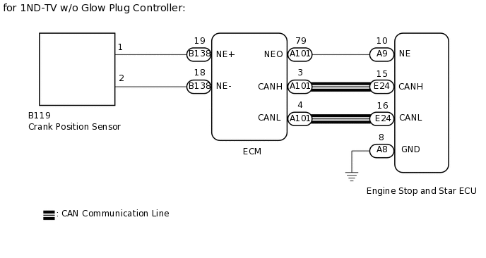
for 1ND-TV w/o Glow Plug Controller:Click hereClick here
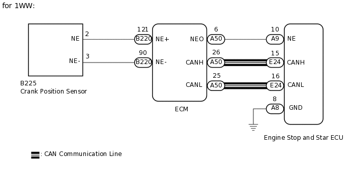
for 1WW:Click hereClick hereClick here
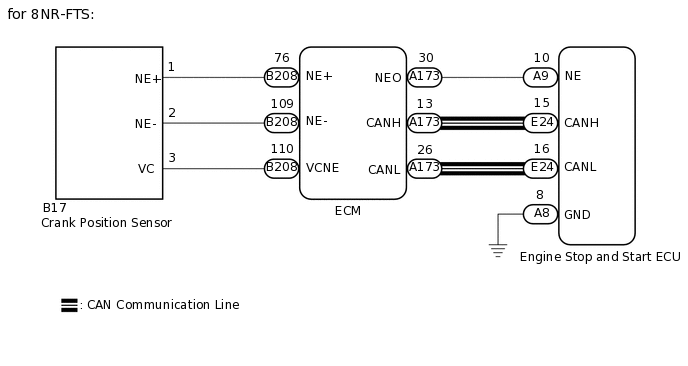
for 8NR-FTS:Click hereClick here
READ VALUE USING GTS (Engine Spd (NE Signal))
Connect the GTS to the DLC3
Start the engine.
Turn the tester on.
Enter the following menus: Powertrain / Stop and Start / Data List / Engine Spd (NE Signal).
According to the display on the GTS, read the Data List.
Powertrain > Stop and Start > Data List
Tester Display
Engine Spd (NE Signal)
OK
Engine speed signal is input (the speeds displayed on the tachometer and the GTS are almost the same).
Result
Proceed to
OK
NG
CHECK HARNESS AND CONNECTOR (ENGINE STOP AND START ECU - ECM)
Turn the ignition switch to OFF
Disconnect the A9 engine stop and start ECU connector.
Disconnect the A173*1, A169*2 or A101*3 A50*4 ECM connector.
*1: for 8NR-FTS
*2: for 1ND-TV (w/ Glow Plug Controller)
*3: for 1ND-TV (w/o Glow Plug Controller)
*4: for 1WW
Measure the resistance according to the value(s) in the table below.
Standard Resistance
Table 1. for 8NR-FTS Tester Connection
Condition
Specified Condition
A9-10 (NE) - A173-30 (NEO)
Always
Below 1 Ω
A9-10 (NE) - Body ground
Always
10 kΩ or higher
A173-30 (NEO) - Body ground
Always
10 kΩ or higher
Table 2. for 1ND-TV (w/ Glow Plug Controller) Tester Connection
Condition
Specified Condition
A9-10 (NE) - A169-6 (NEO)
Always
Below 1 Ω
A9-10 (NE) - Body ground
Always
10 kΩ or higher
A169-6 (NEO) - Body ground
Always
10 kΩ or higher
Table 3. for 1ND-TV (w/o Glow Plug Controller) Tester Connection
Condition
Specified Condition
A9-10 (NE) - A101-79 (NEO)
Always
Below 1 Ω
A9-10 (NE) - Body ground
Always
10 kΩ or higher
A101-79 (NEO) - Body ground
Always
10 kΩ or higher
Table 4. for 1WW Tester Connection
Condition
Specified Condition
A9-10 (NE) - A50-6 (NEO)
Always
Below 1 Ω
A9-10 (NE) - Body ground
Always
10 kΩ or higher
A50-6 (NEO) - Body ground
Always
10 kΩ or higher
Result
Proceed to
OK
NG
NG REPAIR OR REPLACE HARNESS OR CONNECTOR
CHECK HARNESS AND CONNECTOR (ENGINE STOP AND START ECU - BODY GROUND)
Disconnect the A8 engine stop and start ECU connector.
Measure the resistance according to the value(s) in the table below.
Standard Resistance
Tester Connection
Condition
Specified Condition
A8-8 (GND) - Body ground
Always
Below 1 Ω
Result
Proceed to
OK
NG
NG REPAIR OR REPLACE HARNESS OR CONNECTOR
CHECK ENGINE STOP AND START ECU (NE SIGNAL INPUT)
Connect an oscilloscope to the A9-10 (NE) and A8-8 (GND) terminals of the engine stop and start ECU connector.
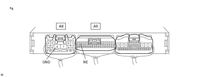
*a
Component with harness connected
(Engine Stop and Start ECU)
-
-
Start the engine.
-
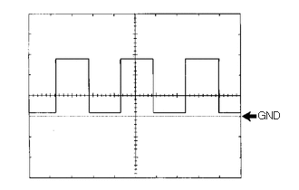
Check the signal waveform according to the condition(s) in the table below.
Item
Condition
Tester Connection
A9-10 (NE) - A8-8 (GND)
Tool Setting
5 V/DIV, 2 ms/DIV
Condition
Idling
Result
Result
Proceed to
Stuck at 0 to 1.5 V
A
Stuck at 8 to 14 V
B
Pulse generation
(See waveform)
C
B GO TO ECD SYSTEM OR EFI SYSTEM
for 1ND-TV w/ Glow Plug Controller:Click hereClick here
for 1ND-TV w/o Glow Plug Controller:Click here
for 1WW:Click hereClick here
for 8NR-FTS:Click here
CHECK ENGINE STOP AND START ECU (NE TERMINAL VOLTAGE)
Disconnect the A173*1, A169*2, A101*3 or A50*4 ECM connector.
*1: for 8NR-FTS
*2: for 1ND-TV (w/ Glow Plug Controller)
*3: for 1ND-TV (w/o Glow Plug Controller)
*4: for 1WW
*a
Component with harness connected
(Engine Stop and Start ECU)
-
-
Turn the ignition switch to ON.
Measure the voltage according to the value(s) in the table below.
Standard Voltage
Tester Connection
Condition
Specified Condition
A9-10 (NE) - A8-8 (GND)
Ignition switch ON
8 to 14 V
Result
Proceed to
OK
NG
Tip:DTCs may be stored during this inspection. Check for DTCs and clear them using the GTS.
OK GO TO ECD SYSTEM OR EFI SYSTEM
for 1ND-TV w/ Glow Plug Controller:Click hereClick here
for 1ND-TV w/o Glow Plug Controller:Click here
for 1WW:Click hereClick here
for 8NR-FTS:Click here