ENGINE UNIT(w/o Glow Plug Controller) REMOVAL
PROCEDURE
REMOVE ENGINE COVER BRACKET (w/ No. 1 Engine Cover)
-
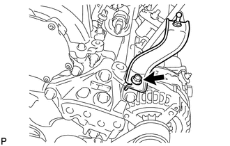
Remove the bolt and engine cover bracket from the engine mounting bracket RH.
-
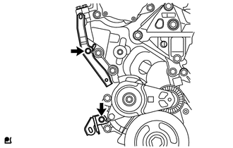
REMOVE GENERATOR ASSEMBLY
-
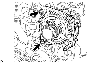
Remove the 2 bolts and generator assembly.
-
REMOVE GENERATOR BRACKET
-
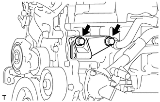
Remove the 2 bolts and generator bracket from the cylinder block sub-assembly.
-
REMOVE EGR WITH COOLER PIPE ASSEMBLY
-
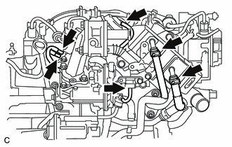
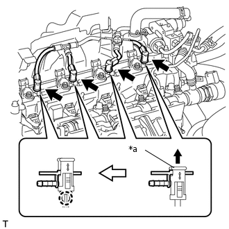
Disconnect the 3 vacuum transmitting hoses from the vacuum switching valve assembly and turbo pressure sensor.
Disconnect the vacuum hose from the EGR with cooler pipe assembly.
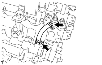
Disconnect the No. 2 oil cooler hose from the EGR with cooler pipe assembly.
Disconnect the No. 2 water by-pass hose from the EGR with cooler pipe assembly.
-
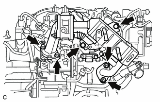
Remove the 4 bolts, 2 nuts and EGR with cooler pipe assembly.
Remove the 2 gaskets from the cylinder head sub-assembly and electric EGR control valve assembly.
-
REMOVE NO. 1 EGR COOLER BRACKET
-
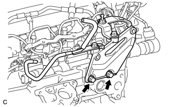
Remove the 2 bolts and No. 1 EGR cooler bracket from the cylinder head sub-assembly.
-
REMOVE HARNESS BRACKET
REMOVE EGR VALVE (ELECTRIC EGR CONTROL VALVE ASSEMBLY)
REMOVE ENGINE OIL LEVEL DIPSTICK
Remove the engine oil level dipstick.
REMOVE ENGINE OIL LEVEL DIPSTICK GUIDE
-
Remove the bolt and engine oil level dipstick guide.
Remove the O-ring from the engine oil level dipstick guide.
-
REMOVE INTAKE AIR CONNECTOR WITH DIESEL THROTTLE BODY
-
Disconnect the vacuum transmitting hose from the hose clamp.
Remove the 2 bolts, 2 nuts and intake air connector with diesel throttle body.
Remove the intake air connector gasket from the cylinder head sub-assembly.
-
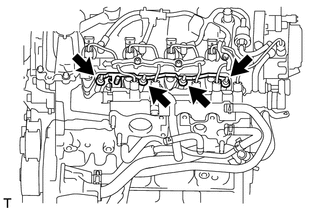
REMOVE NO. 1 INJECTION PIPE SUB-ASSEMBLY
REMOVE NO. 2 INJECTION PIPE SUB-ASSEMBLY
REMOVE NO. 3 INJECTION PIPE SUB-ASSEMBLY
REMOVE NO. 1 GLOW PLUG CONNECTOR
Remove the 4 screw grommets.
-
Remove the 4 nuts and No. 1 glow plug connector.
REMOVE GLOW PLUG ASSEMBLY
-
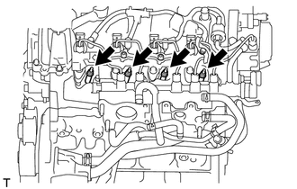
Remove the 4 glow plug assemblies.
-
REMOVE NO. 2 INTAKE MANIFOLD INSULATOR
REMOVE NOZZLE LEAKAGE PIPE SET CLAMP
-
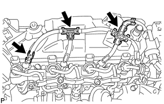
Remove the 3 nozzle leakage pipe set clamps from the nozzle leakage pipe assembly.
-
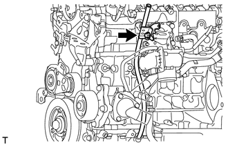
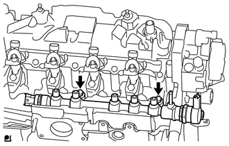
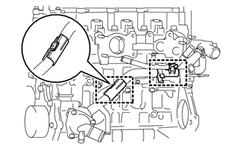
REMOVE NOZZLE LEAKAGE PIPE ASSEMBLY
-
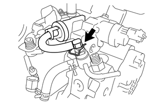
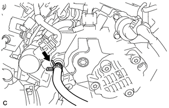
Remove the retainer spring and disconnect the nozzle leakage pipe assembly from the supply pump assembly.
-
*a
Lock Bush
Pull up the lock bush as shown in the illustration and remove the nozzle leakage pipe assembly.
Note:Do not remove the nozzle leakage pipe assembly by pulling the hose. Remove it by holding the lock bush.
-
REMOVE NO. 1 NOZZLE HOLDER CLAMP
REMOVE NOZZLE HOLDER CLAMP SEAT
REMOVE INJECTOR ASSEMBLY
REMOVE INJECTION NOZZLE SEAT
REMOVE FUEL INLET PIPE SUB-ASSEMBLY
REMOVE NO. 2 FUEL HOSE
-
Remove the No. 2 fuel hose.
-
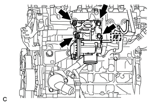
REMOVE SUPPLY PUMP ASSEMBLY
-
Disconnect the No. 1 fuel hose from the supply pump assembly.
-
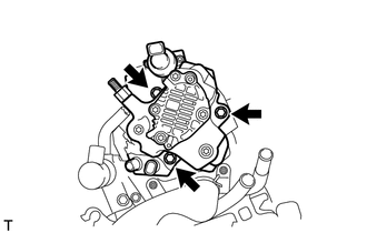
Remove the 3 bolts and supply pump assembly.
-
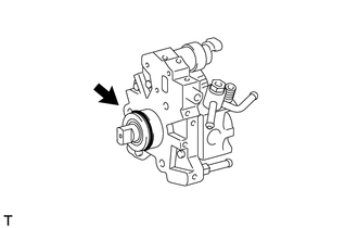
Remove the O-ring from the supply pump assembly.
-
REMOVE NO. 1 SUPPLY PUMP DRIVE COUPLING
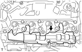
REMOVE COMMON RAIL ASSEMBLY
-
Remove the 2 bolts and common rail assembly from the cylinder head sub-assembly.
Note:Do not remove the fuel pressure sensor and fuel pressure regulator.
-
REMOVE NO. 1 INTAKE MANIFOLD INSULATOR
-
Remove the No. 1 intake manifold insulator.
-
REMOVE NO. 2 CYLINDER HEAD COVER
-
Remove the No. 2 cylinder head cover.
-
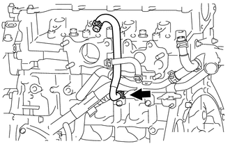
REMOVE OIL COOLER HOSE
-
Remove the oil cooler hose.
-
REMOVE NO. 2 OIL COOLER HOSE
-
Remove the 2 hose clamps.
-
Disconnect the 2 hose clamps and remove the No. 2 oil cooler hose.
-
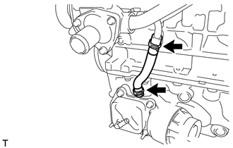
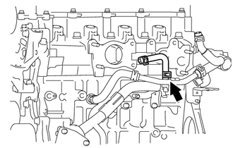
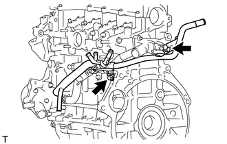
REMOVE NO. 4 WATER BY-PASS HOSE
-
Remove the No. 4 water by-pass hose from the inlet water pipe.
-
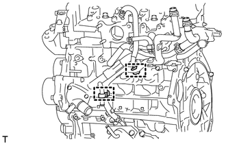
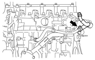
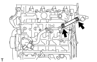
REMOVE NO. 3 WATER BY-PASS HOSE
-
Remove the No. 3 water by-pass hose from the water by-pass pipe sub-assembly.
-
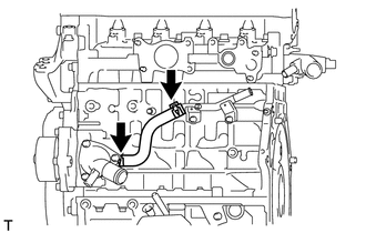
REMOVE NO. 2 WATER BY-PASS HOSE
-
Remove the No. 2 water by-pass hose from the water by-pass pipe sub-assembly.
-
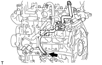
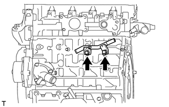
REMOVE WATER BY-PASS HOSE
-
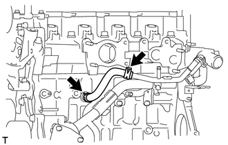
Remove the water by-pass hose.
-
REMOVE WATER BY-PASS PIPE SUB-ASSEMBLY
-
Remove the 2 hose clamps from the water by-pass pipe sub-assembly.
-
Remove the 2 bolts and water by-pass pipe sub-assembly.
Remove the O-ring from the water by-pass pipe sub-assembly.
-
REMOVE INLET WATER HOSE RH
-
Remove the inlet water hose RH.
-
REMOVE INLET WATER HOSE LH
-
Remove the inlet water hose LH.
-
REMOVE INLET WATER PIPE
-
Remove the 2 bolts and inlet water pipe from the cylinder head sub-assembly.
-
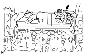
REMOVE VACUUM PUMP ASSEMBLY
-
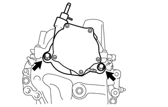
Remove the 2 bolts and vacuum pump assembly.
Remove the 2 O-rings from the vacuum pump assembly.
-
REMOVE CAMSHAFT POSITION SENSOR
-
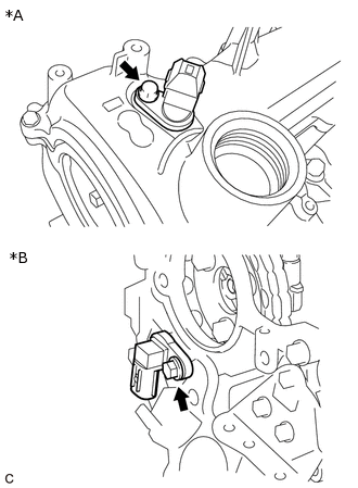
*A
w/o Stop And Start System
*B
w/ Stop And Start System
Remove the bolt and camshaft position sensor.
-
REMOVE HOLE PLUG
-
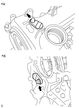
*A
w/ Stop And Start System
*B
w/o Stop And Start System
Remove the bolt and hole plug.
-
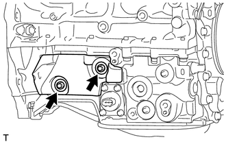
REMOVE V-RIBBED BELT TENSIONER ASSEMBLY
-
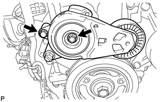
Remove the 2 bolts and V-ribbed belt tensioner assembly.
-
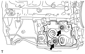
REMOVE HARNESS BRACKET
-
Remove the 2 bolts and 2 harness brackets.
-
REMOVE NO. 5 ENGINE COVER
-
Remove the 2 bolts, 2 washer plates and No. 5 engine cover.
-
REMOVE NO. 2 OIL PAN COVER SILENCER
-
Remove the 2 bolts, 2 washer plates and No. 2 oil pan cover silencer.
-
REMOVE OIL PAN COVER
-
Remove the 2 bolts, 2 washer plates and oil pan cover.
-
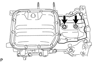
REMOVE STUD BOLT
-
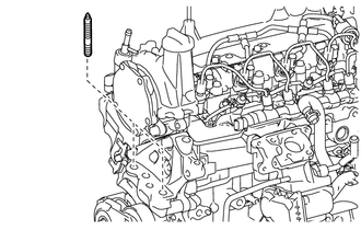
Using an 8 mm socket wrench, remove the 2 stud bolts from the engine mounting bracket RH.
-