ECD SYSTEM(w/ Glow Plug Controller) FREEZE FRAME DATA
DESCRIPTION
The ECM records vehicle and driving condition information as freeze frame data the moment a DTC is stored. When troubleshooting, freeze frame data can help determine if the vehicle was moving or stationary, if the engine was warmed up or not, and other data from the time of a malfunction.
Tip:If it is impossible to duplicate the problem even though a DTC is detected, confirm the freeze frame data.
-
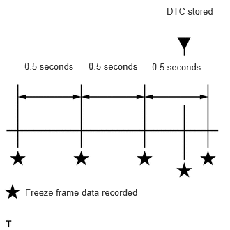
The ECM records engine conditions in the form of freeze frame data every 0.5 seconds. Using the GTS, 5 separate sets of freeze frame data can be checked.
-
3 data sets before the DTC was stored.
1 data set when the DTC was stored.
1 data set after the DTC was stored.
These data sets can be used to simulate the condition of the vehicle around the time of the occurrence of the malfunction. The data may assist in identifying the cause of the malfunction, and in judging whether it was temporary or not.
-
LIST OF FREEZE FRAME DATA
Powertrain > Engine and ECT
Tester Display
Measurement Item
Diagnostic Note
Vehicle Speed
Vehicle speed
Speed indicated on speedometer
Engine Speed
Engine speed
-
Calculate Load
Calculated load by ECM
-
MAF
Air flow rate from mass air flow meter
-
Atmosphere Pressure
Atmospheric pressure value
-
MAP
Absolute pressure inside intake manifold
-
Coolant Temp
Engine coolant temperature
If -30°C (-22°F) or less, sensor circuit is open
If 120°C (248°F) or higher, sensor circuit is shorted
Intake Air
Intake air temperature
If -40°C (-40°F), sensor circuit is open
If 120°C (248°F) or higher, sensor circuit is shorted
Intake Air Temp (Turbo) Supported
Status of intake air temperature after intercooler supported
-
Intake Air Temp (Turbo)
Intake air temperature after intercooler
If -30°C (-22°F) or less, sensor circuit is open
If 150°C (302°F) or higher, sensor circuit is shorted
Engine Run Time
Engine run time
-
Initial Engine Coolant Temp
Initial engine coolant temperature
-
Initial Intake Air Temp
Initial intake air temperature
-
Battery Voltage
Battery voltage
-
Alternate Duty Ratio
Alternator generation duty ratio
-
Pre Glow
Pre glow operation
-
After Glow
After glow operation
-
Engine Oil Pressure
Engine oil pressure value
-
Accel Position
Accelerator position status
-
Accel Sens. No.1 Volt %
Accelerator position No. 1
-
Accel Sens. No.2 Volt %
Accelerator position No. 2
-
Target Throttle Position Supported
Status of target throttle position supported
-
Target Throttle Position
Target throttle position
-
Target Throttle Position #2 Supported
Status of target throttle position No. 2 supported
-
Target Throttle Position #2
Target throttle position No. 2
-
Actual Throttle Position Supported
Status of actual throttle position supported
-
Actual Throttle Position
Actual throttle position
-
Actual Throttle Position #2 Supported
Status of actual throttle position No. 2 supported
-
Actual Throttle Position #2
Actual throttle position No. 2
-
Throttle Motor DUTY
Diesel throttle motor actuator duty
-
Throttle Close Learning Val.
Throttle fully closed position learned value
-
Throttle Sensor Volt %
Throttle position sensor output voltage
-
Injection Volume
Injection volume
-
Injection Feedback Val #1
Injection volume correction for No. 1 cylinder
-
Injection Feedback Val #2
Injection volume correction for No. 2 cylinder
-
Injection Feedback Val #3
Injection volume correction for No. 3 cylinder
-
Injection Feedback Val #4
Injection volume correction for No. 4 cylinder
-
Pilot 1 Injection Period
Pilot 1 injection period
-
Pilot 2 Injection Period
Pilot 2 injection period
-
Main Injection Period
Main injection period
-
After Injection Period
After injection period
-
Pilot 1 Injection Timing
Pilot 1 injection timing
-
Pilot 2 Injection Timing
Pilot 2 injection timing
-
Main Injection Timing
Main injection timing
-
After Injection Timing
After injection timing
-
Injection Pressure Correction
Injection pressure feedback compensation volume
-
Target Common Rail Pressure Supported
Status of target common rail pressure supported
-
Target Common Rail Pressure
Target common rail pressure
-
Common Rail Pressure Supported
Status of common rail pressure supported
-
Common Rail Pressure
Common rail pressure
-
Fuel Temperature Supported
Status of fuel temperature supported
-
Fuel Temperature
Fuel temperature
-
Target Pump SCV Current
Pump current target final value
-
Pressure Discharge Valve
Pressure control valve operation signal
-
AFS Current B1S1
Air fuel ratio sensor (for sensor 1) current
-
AF Sensor Learning Value
Air fuel ratio sensor (for sensor 1) learning value
-
AF Sensor Learning Value B1S2
Air fuel ratio sensor (for sensor 2) learning value
-
Target EGR Valve Pos Supported
Status of target EGR valve position supported
-
Target EGR Valve Pos
EGR valve target opening angle
-
Target EGR Valve Pos #2 Supported
Status of target EGR valve position No. 2 supported
-
Target EGR Valve Pos #2
EGR valve target opening angle No. 2
-
Actual EGR Valve Pos Supported
Status of actual EGR valve position supported
-
Actual EGR Valve Pos
EGR valve position
-
Actual EGR Valve Pos #2 Supported
Status of actual EGR valve position No. 2 supported
-
Actual EGR Valve Pos #2
EGR valve position No. 2
-
EGR Position Sensor
EGR valve position sensor voltage
-
EGR Motor Duty #1
EGR valve motor duty ratio
-
EGR Close Lrn. Val.
EGR fully closed position learned value
-
EGR Operation Prohibit
EGR Active Test operation prohibit
-
EGR Cooler Bypass VSV
EGR cooler bypass valve VSV operation
-
EGR Cooler Bypass Position
EGR cooler bypass valve position
-
Target Booster Pressure Supported
Status of target boost pressure supported
-
Target Booster Pressure
Target boost pressure
-
VN Turbo Command Supported
Status of VN turbo command supported
-
Target VN Turbo Position
Target VN turbo position
-
VN Turbo Command #2 Supported
Status of VN turbo command No. 2 supported
-
Target VN Turbo Position #2
Target VN turbo position No. 2
-
Actual VN Position Supported
Status of actual VN turbo position supported
-
Actual VN Turbo Position
Actual VN turbo position
The actual VN turbo position is controlled to reach the target (Target VN Turbo Position).
Actual VN Position #2 Supported
Status of actual VN turbo position No. 2 supported
-
Actual VN Turbo Position #2
Actual VN turbo position No. 2
-
VN Close Learn Value
VN turbocharger closed learning value
-
VN Turbo Max Angle
VN turbo maximum opening angle
-
VN Turbo Min Angle
VN turbo minimum opening angle
-
Exhaust Temperature B1S1 Supported
Status of exhaust gas temperature (bank 1 sensor 1) supported
-
Exhaust Temperature B1S1
Exhaust gas temperature of NSR (NOx Storage Reduction) catalyst
If 50°C (122°F), sensor circuit is open
If 950°C (1742°F), sensor circuit is shorted
Exhaust Temperature B1S2 Supported
Status of exhaust gas temperature (bank 1 sensor 2) supported
-
Exhaust Temperature B1S2
Exhaust gas temperature of DPF catalyst
If 50°C (122°F), sensor circuit is open
If 950°C (1742°F), sensor circuit is shorted
Exhaust Temperature B1S3 Supported
Status of exhaust gas temperature (bank 1 sensor 3) supported
-
Exhaust Temperature B1S3
Exhaust gas temperature
-
DPF Differential Pressure Supported
Status of DPF differential pressure supported
-
DPF Differential Pressure
DPF differential pressure sensor output
-
Catalyst Differential Press
Catalyst differential pressure
-
Diff. Press. Sensor Corr.
Differential pressure sensor correction
-
DPNR Status Reju (S)
Sulfur regeneration status
-
DPNR/DPF Status Reju(PM)
PM regeneration status
-
Sulfur Accumulation Ratio
Sulfur accumulation ratio
-
PM Accumulation Ratio
PM accumulation ratio
-
Starter Signal
Starter signal
-
Clutch Switch
Clutch switch
-
Stop Light Switch
Stop light switch
-
Shift Indication Enable
Shift indication enable
-
A/C Signal
A/C (Air Conditioner) signal
-
Immobiliser Communication
Immobiliser communication
-
ASL Switch
Speed limiter switch signal
-
TC Terminal
TC terminal status
-
Time after DTC Cleared
Time after DTC cleared
-
Distance from DTC Cleared
Distance after DTC cleared
-
Warmup Cycle Cleared DTC
Warm-up cycle after DTC cleared
-
IG OFF Elapsed Time
Time after engine switch off
-
TC and TE1
TC and CG (TE1) terminals of DLC3
-
Total Distance Traveled
Total distance traveled
-
Engine Speed (Starter Off)
Engine speed when starter off
This is the engine speed immediately after starting the engine.
Glow Request Lighting Time
Indicates the length of time the glow indicator light was on
-
IG-ON Time
Elapsed time to start engine after the ignition switch was turned to ON
This shows the condition when the glow turn on request occurred. If a malfunction occurred during a cold engine start (below 0°C [32°F]), based on IG-ON Time it can be determined whether the request was made after the glow plug and glow indicator turned off or not.
MAF Low
Status of mass air flow rate low
This shows that the intake air volume measured by the mass air flow meter was insufficient, resulting in a continuous reduction of injection volume.
If the intake system is clogged, the pipes are not properly connected, intake air volume is low due to excessive EGR, or the mass air flow meter has deteriorated, the measured intake air volume may be lower than the normal volume.
Boost Pressure Low
Status of boost pressure Low
This shows that the boost pressure (turbocharger boost pressure) was less than the target, resulting in a continuous reduction of injection volume.
Engine Coolant Temp High
Status of engine coolant temperature high
This shows that there was a continuous reduction of injection volume due to high engine coolant temperature (overheating).
MAF/Estimate MAF Ratio
Mass air flow rate (actual) / mass air flow rate (estimated) value
This shows the calculated intake air volume based on the intake air volume measured by the mass air flow meter, manifold pressure and intake air temperature.
Rough Idle #1
Status of No. 1 cylinder rough idle
This shows that the idle speed of this cylinder is lower than the other cylinder.
Rough Idle #2
Status of No. 2 cylinder rough idle
This shows that the idle speed of this cylinder is lower than the other cylinder.
Rough Idle #3
Status of No. 3 cylinder rough idle
This shows that the idle speed of this cylinder is lower than the other cylinder.
Rough Idle #4
Status of No. 4 cylinder rough idle
This shows that the idle speed of this cylinder is lower than the other cylinder.
Engine Starting Time
Time elapsed before engine starts (after starter turns on until engine speed reaches 400 rpm)
-
Engine Start Hesitation
History of hesitation during engine start
-
Low Rev for Eng Start
History of low engine speed after engine start
-
ACT VSV
A/C cut status for Active Test
-
Electric Fan Motor
Electric fan motor operation
-
Brake Override System
Brake override system status
-
Immobiliser Fuel Cut History
Status of immobiliser fuel cut
If this item was ON when DTC P1604 was detected, this means that the engine could not start due to immobiliser operation.
Electrical Load Signal 1
Electrical load signal
-
Electrical Load Signal 2
Electrical load signal
-
Shift SW Status (R Range)
Back-up light switch status
-
MT Down Shift Indication
Manual transmission shift down indication
-
MT Up Shift Indication
Manual transmission shift up indication
-
Stop&Start of Eng State
Engine status of stop and start system
-