SFI SYSTEM, Diagnostic DTC:P024313
| DTC Code | DTC Name |
|---|---|
| P024313 | Turbocharger/Supercharger Wastegate Solenoid "A" Circuit Open |
DESCRIPTION
The waste gate valve is built into the turbine housing and is operated by the vacuum regulating valve assembly. The ECM uses duty control to open and close the vacuum regulating valve assembly. The amount of opening is controlled according to the operation status.
When the engine is started, the degree of opening of the waste gate valve is optimally adjusted so that the hot combustion gases passing through it flow directly into the catalyst. In the low-engine-load operating range, the waste gate valve opens to lower the exhaust manifold pressure to reduce pumping losses and improve fuel economy. Closing the waste gate valve increases the torque in the engine low-speed, high-load range to improve response during acceleration.
DTC No. |
Detection Item |
DTC Detection Condition |
Trouble Area |
MIL |
Memory |
Note |
|---|---|---|---|---|---|---|
P024313 |
Turbocharger/Supercharger Wastegate Solenoid "A" Circuit Open |
Open or short in vacuum regulating valve assembly circuit for 1 second or more (1 trip detection logic) |
|
Does not come on |
DTC stored |
SAE Code: P0243 |
MONITOR DESCRIPTION
This DTC is stored when an open or short is detected in the vacuum regulating valve assembly circuit. When an excessively high or low duty cycle malfunction occurs in the vacuum regulating valve assembly during vacuum regulating valve assembly drive, the ECM stores this DTC.
MONITOR STRATEGY
Required Sensors/Components (Main) |
Vacuum regulating valve assembly |
Frequency of Operation |
Continuous |
CONFIRMATION DRIVING PATTERN

Connect the GTS to the DLC3.
Turn the ignition switch to ON and turn the GTS on.
Clear the DTCs (even if no DTCs are stored, perform the clear DTC procedure).
Turn the ignition switch off and wait for at least 30 seconds.
Turn the ignition switch to ON and turn the GTS on.
Start the engine and warm it up until the engine coolant temperature reaches 75°C (167°F) or higher [A].
Accelerate to 50 km/h (31 mph) or more with the accelerator pedal fully depressed [B].
CAUTION:When performing the confirmation driving pattern, obey all speed limits and traffic laws.
Enter the following menus: Powertrain / Engine / Trouble Codes [C].
Read the pending DTCs.
Tip:If a pending DTC is output, the system is malfunctioning.
If a pending DTC is not output, perform the following procedure.
Enter the following menus: Powertrain / Engine / Utility / All Readiness.
Input the DTC: P024313.
Check the DTC judgment result.
GTS Display
Description
NORMAL
DTC judgment completed
System normal
ABNORMAL
DTC judgment completed
System abnormal
INCOMPLETE
DTC judgment not completed
Perform driving pattern after confirming DTC enabling conditions
N/A
Unable to perform DTC judgment
Number of DTCs which do not fulfill DTC preconditions has reached ECU memory limit
Tip:If the judgment result shows NORMAL, the system is normal.
If the judgment result shows ABNORMAL, the system has a malfunction.
If the judgment result shows INCOMPLETE or N/A, perform steps [B] and [C] again.
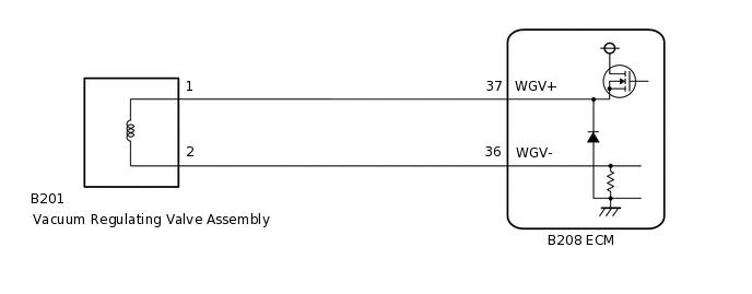
WIRING DIAGRAM
CAUTION / NOTICE / HINT
Read freeze frame data using the GTS. The ECM records vehicle and driving condition information as freeze frame data the moment a DTC is stored. When troubleshooting, freeze frame data can help determine if the vehicle was moving or stationary, if the engine was warmed up or not, if the air fuel ratio was lean or rich, and other data from the time the malfunction occurred.
PROCEDURE
INSPECT VACUUM REGULATING VALVE ASSEMBLY
Inspect the vacuum regulating valve assembly.
Result
Proceed to
OK
NG
CHECK HARNESS AND CONNECTOR (VACUUM REGULATING VALVE ASSEMBLY - ECM)
Disconnect the vacuum regulating valve assembly connector.
Disconnect the ECM connector.
Measure the resistance according to the value(s) in the table below.
Standard Resistance
Tester Connection
Condition
Specified Condition
B201-1 - B208-37 (WGV+)
Always
Below 1 Ω
B201-2 - B208-36 (WGV-)
Always
Below 1 Ω
B201-1 or B208-37 (WGV+) - Body ground and other terminals
Always
10 kΩ or higher
B201-2 or B208-36 (WGV-) - Body ground and other terminals
Always
10 kΩ or higher
Result
Proceed to
OK
NG
NG REPAIR OR REPLACE HARNESS OR CONNECTOR
CHECK WHETHER DTC OUTPUT RECURS (DTC P024313)
Connect the GTS to the DLC3.
Turn the ignition switch to ON.
Turn the GTS on.
Clear the DTCs.
Powertrain > Engine > Clear DTCs
Turn the ignition switch off and wait for at least 30 seconds.
Start the engine and warm it up.
Turn the GTS on.
Drive the vehicle in accordance with the driving pattern described in Confirmation Driving Pattern.
Enter the following menus: Powertrain / Engine / Utility / All Readiness.
Powertrain > Engine > Utility
Tester Display
All Readiness
Input the DTC: P024313.
Check the DTC judgment result.
Result
Result
Proceed to
NORMAL
(DTCs are not output)
A
ABNORMAL
(DTC P024313 is output)
B