EMISSION CONTROL SYSTEM DETAILS
-
FUNCTION OF MAIN COMPONENTS
-
The main components of the emission control system are as follows:
Component Quantity Function Oxidation Catalyst*1 2*2 Cleans the exhaust gas particulates, HC and CO. 1*3 Diesel Particulate Filter (DPF) Catalyst*2 1 Captures the PM. ECM 1 Controls the emission control system based on signals from each sensor. Electric EGR Control Valve Assembly 1 Actuated by the ECM, this valve controls the flow rate of EGR gas.*2 Actuated by the ECM via the E-VRV, this valve controls the flow rate of EGR gas.*4 EGR Valve Position Sensor (Built into Electric EGR Control Valve Assembly) 1 Detects the EGR valve position. Diesel Throttle Valve 1 Actuated by the ECM, this valve controls the flow rate of EGR gas. EGR Cooler*5 1 Cools EGR gas. No. 2 EGR Valve Assembly (EGR Cooler Bypass Switching Valve)*5 1 Switches the flow passage of EGR gas in 2 stages. Exhaust Fuel Addition Injector Assembly*2 1 Injects fuel into the turbine outlet elbow after the turbocharger. Differential Pressure Sensor*2 1 Monitors the differential pressure before and after the DPF catalyst to detect whether the DPF catalyst is clogged. Exhaust Gas Temperature Sensor*2 3 Located before the oxidation catalyst, and before and after the DPF catalyst, these sensors detect the exhaust gas temperature. Air Fuel Ratio Sensor (Bank 1, Sensor 1)*2 1 Detects the oxygen concentration in exhaust gas. Glow Plug Controller*2 1 Operates the glow plug assembly in accordance with a signal from the ECM during the catalyst support control. Glow Plug Assembly*2 4 Actuated by the glow plug controller, the glow plug assembly heats the air in the cylinder.
-
*1: Models with 2KD-FTV engine compliant with EURO 2 emission regulations, models compliant with EURO 2 emission regulations with variable nozzle vane type turbocharger, models compliant with EURO 5 and EURO 4 emission regulations and KUN15R-CRMSHN
-
*2: Models compliant with EURO 5 emission regulations
-
*3: Models with 2KD-FTV engine compliant with EURO 2 emission regulations, models compliant with EURO 2 emission regulations with variable nozzle vane type turbocharger, models compliant with EURO 4 emission regulations and KUN15R-CRMSHN
-
*4: Models compliant with EURO 4 and EURO 2 emission regulations
-
*5: Models compliant with EURO 5 and EURO 4 emission regulations
-
-
-
SYSTEM CONTROL
-
EGR System
-
Based on the signals received from the sensors, the ECM determines the EGR volume via the electric EGR control valve assembly and No. 2 EGR valve assembly (EGR cooler bypass switching valve)* in accordance with the engine condition.
-
*: Models compliant with EURO 5 and EURO 4 emission regulations
-
-
-
Catalyst Support Control (Models Compliant with EURO 5 Emission Regulations)
-
Based on the signals received from the sensors, the ECM controls the exhaust fuel addition injector assembly to purify the Particulate Matter (PM).
-
-
Air Fuel Ratio Sensor Heater Control (Models Compliant with EURO 5 Emission Regulations)
-
Maintains the temperature of the air fuel ratio sensor at an appropriate level to increase accuracy of detection of the oxygen concentration in exhaust gas.
-
-
-
FUNCTION
-
EGR System
-
This system is designed to help reduce and control NOx formation due to a reduction of peak temperature in the engine combustion chamber, which is accomplished by the introduction of an amount of inert gas into the intake manifold.
-
-
Catalyst Support Control (Models Compliant with EURO 5 Emission Regulations)
-
The ECM judges the DPF catalyst condition based on signals from the mass air flow meter, engine coolant temperature sensor, 3 exhaust gas temperature sensors, differential pressure sensor, and air fuel ratio sensor to control the injector assemblies and exhaust fuel addition injector assembly for catalyst support control.
-
-
-
CONSTRUCTION
-
Oxidation Catalyst
-
An oxidation catalyst is used to clean the exhaust gas particulates, HC, and CO. The table below describes the location of the catalyst:
Engine Emission Regulations Location of Catalyst Integrated with Front Exhaust Pipe Below Exhaust Manifold 2KD-FTV EURO 2 - ○ - - - 2KD-FTV High Version EURO 5 ○ ○ EURO 4 ○ - EURO 2
w/ Variable Nozzle Vane Type Turbocharger
○ - EURO 2
w/ Wastegate Valve Type Turbocharger
KUN15R-CRMSHN - ○ Except KUN15R-CRMSHN - - - - - 
Text in Illustration *A Models Compliant with EURO 5 Emission Regulations *B Models Compliant with EURO 4 Emission Regulations *C Models with Variable Nozzle Vane Type Turbocharger *D Models with Wastegate Valve Type Turbocharger *E Models with 2KD-FTV Engine Compliant with EURO 2 Emission Regulations and KUN15R-CRMSHN *F Models Compliant with EURO 2 Emission Regulations with Variable Nozzle Vane Type Turbocharger *1 Turbine Outlet Elbow *2 No. 2 Turbine Outlet Elbow *3 Oxidation Catalyst *4 Front Exhaust Pipe Assembly *5 Exhaust Manifold Converter Sub-assembly - -
-
-
DPF Catalyst (Models Compliant with EURO 5 Emission Regulations)
-
A DPF catalyst is used to capture the PM.
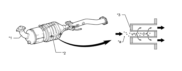
Text in Illustration *1 Front Exhaust Pipe Assembly *2 DPF Catalyst *3 Filter - - *a PM - - 
Exhaust Gas - -
-
-
Electric EGR Control Valve Assembly (Models Compliant with EURO 5 Emission Regulations)
-
A DC motor type electric EGR control valve assembly is used. The placement of the electric EGR control valve assembly at the intersection between the intake passage and EGR bypass facilitates the uniform distribution of EGR gas and intake air.
-
An EGR valve position sensor is provided in the electric EGR control valve assembly. This sensor enables EGR valve control at a higher level of precision by detecting the opening angle of the EGR valve.
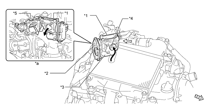
Text in Illustration *1 Electric EGR Control Valve Assembly *2 EGR Valve Position Sensor *3 DC Motor Portion *4 EGR Valve *5 Diesel Throttle Body Assembly - - *a View from Back Side - - 
Intake Air EGR Gas 
Front - -
-
-
Electric EGR Control Valve Assembly (Models Compliant with EURO 4 and EURO 2 Emission Regulations)
-
A vacuum actuated type electric EGR control valve assembly is used.
-
The electric EGR control valve assembly is provided midstream in the intake air passage. By cooling the electric EGR control valve assembly in this manner, a greater volume of exhaust gas can be processed.
-
An EGR valve position sensor is provided in the electric EGR control valve assembly in order to directly measure the actual amount of the valve opening. This measurement is then input into the ECM in order to improve the precision of EGR control.
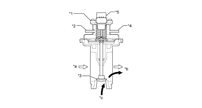
Text in Illustration (Models Compliant with EURO 4 Emission Regulations and Models Compliant with EURO 2 Emission Regulations with Variable Nozzle Vane Type Turbocharger:) *1 Electric EGR Control Valve Assembly *2 Vacuum Port *3 EGR Valve *4 Air Port *5 EGR Valve Position Sensor - - *a From Diesel Throttle Body *b To Intake Manifold *c From EGR Pipe Sub-assembly - - Intake Air EGR Gas 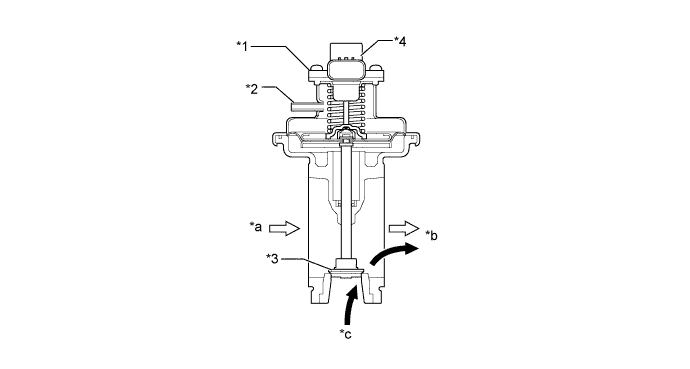
Text in Illustration (Models Compliant with EURO 2 Emission Regulations with Wastegate Valve Type Turbocharger:) *1 Electric EGR Control Valve Assembly *2 Vacuum Port *3 EGR Valve *4 EGR Valve Position Sensor *a From Diesel Throttle Body *b To Intake Manifold *c From EGR Pipe Sub-assembly - - Intake Air EGR Gas
-
-
EGR Pipe Sub-assembly and No. 2 EGR Valve Assembly (Models Compliant with EURO 5 and EURO 4 Emission Regulations)
-
A water-cooled type EGR cooler is used in the EGR pipe sub-assembly between the cylinder head and EGR valve. In the water-cooled type EGR cooler, engine coolant flows through the eight-layered*1 or six-layered*2 gas passage to cool down the EGR gas.
-
*1: Models compliant with EURO 5 emission regulations
-
*2: Models compliant with EURO 4 emission regulations
-
-
A No. 2 EGR valve assembly (EGR cooler bypass switching valve) is used. If EGR gas is cooled down in the EGR cooler with light engine load and low engine coolant temperature, compression air temperature decreases. To prevent this, the EGR gas passage is switched by the EGR cooler bypass switching valve. The EGR passage is switched in 2 stages.
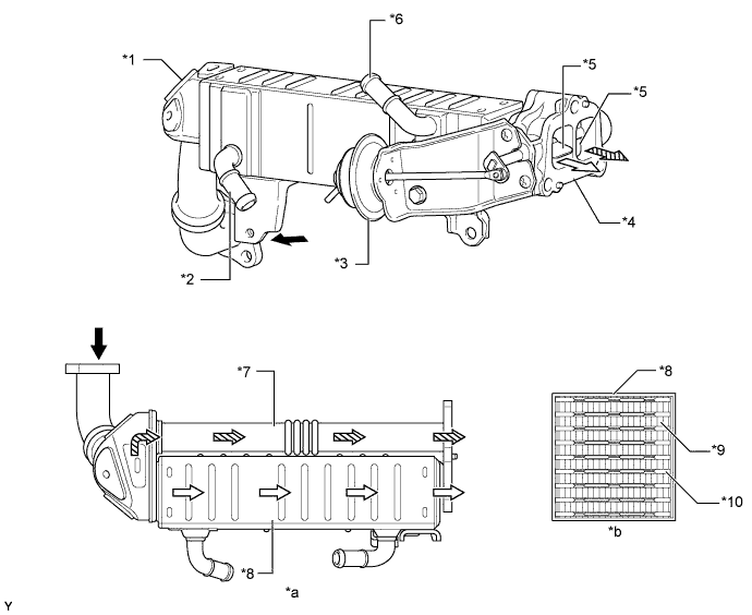
Text in Illustration (Models Compliant with EURO 5 Emission Regulations:) *1 EGR Pipe Sub-assembly *2 Engine Coolant Inlet *3 Actuator for EGR Cooler Bypass Switching Valve *4 No. 2 EGR Valve Assembly *5 EGR Cooler Bypass Switching Valve *6 Engine Coolant Outlet *7 Bypass Passage *8 EGR Cooler *9 EGR Gas Passage *10 Engine Coolant Passage *a View from Upper Side *b EGR Cooler Cross Section EGR Gas EGR Gas (through EGR Cooler) EGR Gas (through Bypass Passage) - - 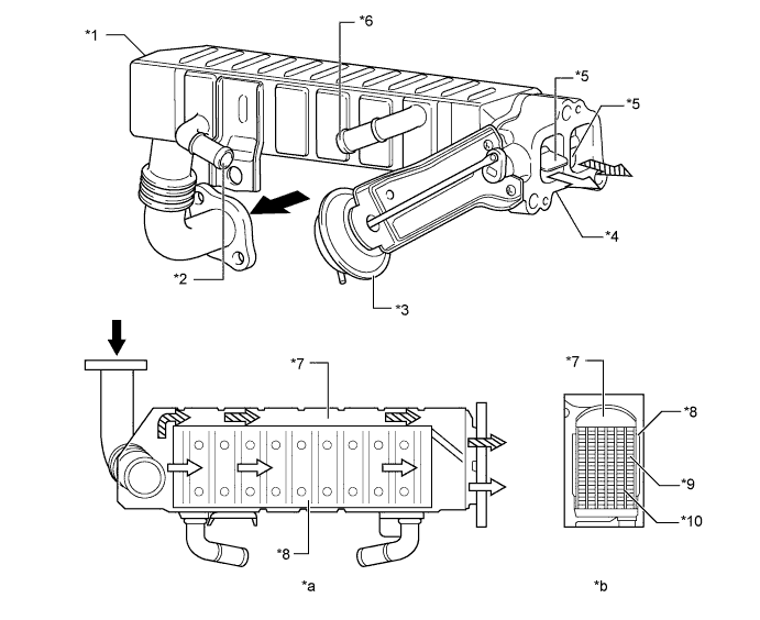
Text in Illustration (Models Compliant with EURO 4 Emission Regulations:) *1 EGR Pipe Sub-assembly *2 Engine Coolant Inlet *3 Actuator for EGR Cooler Bypass Switching Valve *4 No. 2 EGR Valve Assembly *5 EGR Cooler Bypass Switching Valve *6 Engine Coolant Outlet *7 Bypass Passage *8 EGR Cooler *9 EGR Gas Passage *10 Engine Coolant Passage *a View from Upper Side *b Cross Section EGR Gas EGR Gas (through EGR Cooler) EGR Gas (through Bypass Passage) - -
-
-
Exhaust Fuel Addition Injector Assembly (Models Compliant with EURO 5 Emission Regulations)
-
An exhaust fuel addition injector is installed on the turbine outlet elbow after the turbocharger. This injector supplies additional fuel into the turbine outlet elbow and maintains the proper catalyst temperature for the purpose of PM recovery.
-
An exhaust fuel addition injector assembly consists of a needle valve body, a needle valve, and a solenoid valve.

Text in Illustration *1 Solenoid Valve *2 Needle Valve *3 Needle Valve Body - -
-
-
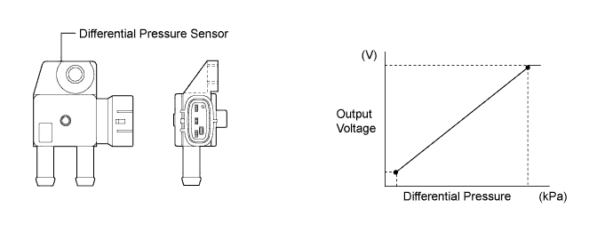
Differential Pressure Sensor (Models Compliant with EURO 5 Emission Regulations)
-
The differential pressure sensor measures the pressure differences between before and after the DPF catalyst with PM in order to detect clogging.
-
The sensor is mounted on the transmission. The DPF catalyst and the sensor are connected with pipes and hoses.
-
-
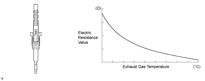
Exhaust Gas Temperature Sensor (Models Compliant with EURO 5 Emission Regulations)
-
An exhaust gas temperature sensor, which is a thermistor type, is installed before the oxidation catalyst, before the DPF catalyst and after the DPF catalyst, in order to detect the temperature of the exhaust gas.
-
-
Air Fuel Ratio Sensor (Models Compliant with EURO 5 Emission Regulations)
-
The planar type air fuel ratio sensor is used.
-
The planar type air fuel ratio sensor uses alumina, which excels in heat conductivity and insulation, to integrate the sensor element with the heater, thus improving the warm-up performance of the sensor.
-
This sensor is based on a sensor developed for gasoline engines. The cover has been changed for diesel engine application in order to eliminate the influences of the sensor temperature and the PM. This sensor, which is mounted after the DPF catalyst, detects the air fuel ratio after the gas has been reduced.
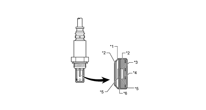
Text in Illustration *1 Diffusion Resistance Layer *2 Alumina *3 Atmosphere *4 Heater *5 Platinum Electrode *6 Sensor Element (Zirconia) -
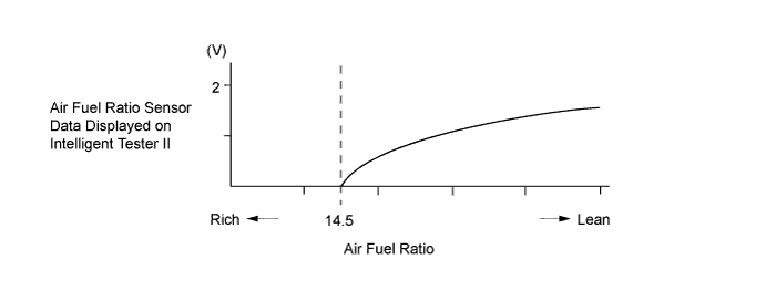
The air fuel ratio sensor data is approximately proportional to the existing air fuel ratio. The air fuel ratio sensor converts the oxygen density to the current and sends it to the ECM.
-
As a result, the detection precision of the air fuel ratio has been improved. The air fuel ratio sensor data can be read using an intelligent tester II.
-
-
-
OPERATION
-
EGR System
-
On the models compliant with EURO 5 emission regulations, EGR system carries out the following controls:
-
The ECM actuates the electric EGR control valve assembly, which regulates volume of EGR gas recirculation, in accordance with the engine conditions.
-
The ECM switches the bypass passage of the EGR pipe sub-assembly via the VSV (for EGR cooler bypass switching valve) in 2 stages in order to optimize the temperature of the EGR gas and clean exhaust gases.
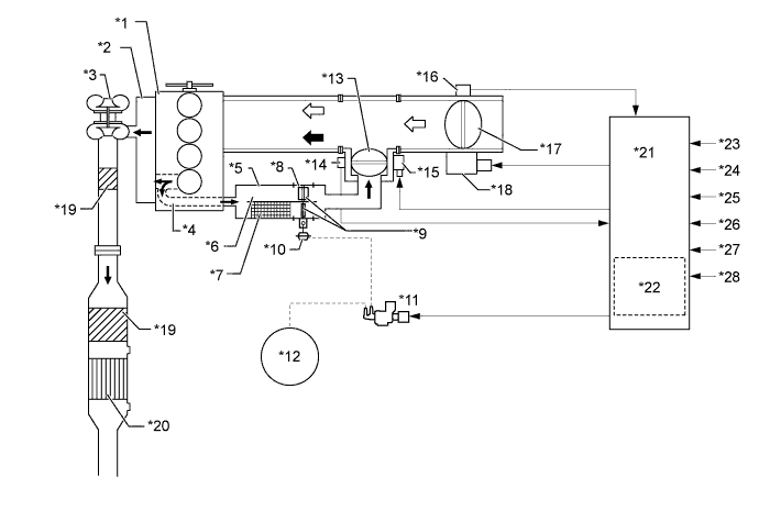
Text in Illustration *1 Engine *2 Exhaust Manifold *3 Turbocharger Sub-assembly *4 EGR Passage in Cylinder Head *5 EGR Pipe Sub-assembly *6 Bypass Passage *7 EGR Cooler *8 No. 2 EGR Valve Assembly *9 EGR Cooler Bypass Switching Valve *10 Actuator for EGR Cooler Bypass Switching Valve *11 VSV (for EGR Cooler Bypass Switching Valve) *12 Vacuum Pump *13 EGR Valve *14 EGR Valve Position Sensor *15 DC Motor for EGR Valve Control *16 Throttle Position Sensor *17 Diesel Throttle Valve *18 Throttle Control Motor *19 Oxidation Catalyst *20 Diesel Particulate Filter (DPF) Catalyst *21 ECM *22 Atmospheric Pressure Sensor *23 Crank Position Sensor *24 Accelerator Pedal Position Sensor *25 Engine Coolant Temperature Sensor *26 Turbo Pressure Sensor *27 Intake Air Temperature Sensor *28 Intake Mass Air Flow Meter Sub-assembly Exhaust Gas Intake Air
-
-
On the models compliant with EURO 4 and EURO 2 emission regulations, EGR system carries out the following controls:
-
By sensing the engine driving conditions and actual amount of EGR valve opening, the ECM electrically operates the E-VRV (for EGR valve control) and VSV (for EGR valve close)*, which control the magnitude of vacuum introduced into the diaphragm of the electric EGR control valve assembly. In addition, the ECM controls the diesel throttle valve opening position using the throttle control motor. As a result, the amount of recirculating exhaust gas is regulated. EGR valve opening lift is controlled by modulated negative pressure.
-
*: Models compliant with EURO 4 emission regulations and models compliant with EURO 2 emission regulations with variable nozzle vane type turbocharger
-
On the models compliant with EURO 4 emission regulations and models compliant with EURO 2 emission regulations with variable nozzle vane type turbocharger, the VSV (for EGR valve close) is activated when the EGR control is stopped, in order to introduce the atmospheric pressure to the diaphragm of electric EGR control valve assembly and improve EGR valve closure response to maintain driveability.
-
On the models compliant with EURO 4 emission regulations, the ECM switches the bypass passage of the EGR pipe sub-assembly via the VSV (for EGR cooler bypass switching valve) in 2 stages in order to optimize the temperature of the EGR gas and clean exhaust gases.
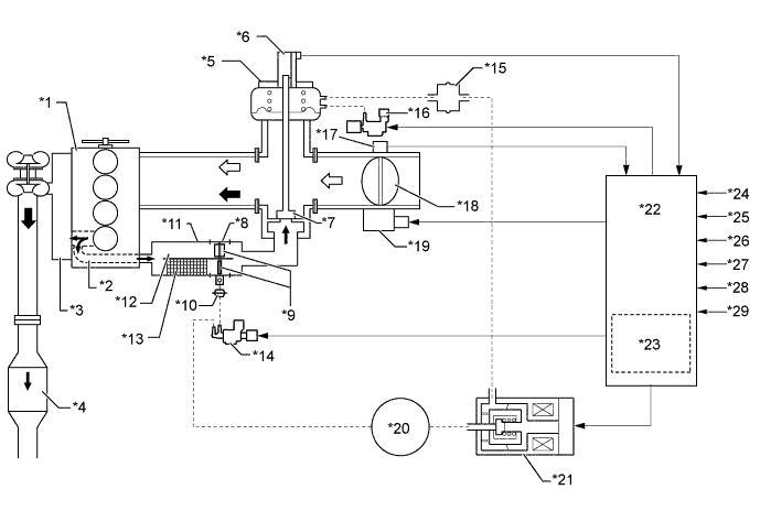
Text in Illustration (Models Compliant with EURO 4 Emission Regulations:) *1 Engine *2 EGR Passage in Cylinder Head *3 Exhaust Manifold *4 Oxidation Catalyst *5 Electric EGR Control Valve Assembly *6 EGR Valve Position Sensor *7 EGR Valve *8 No. 2 EGR Valve Assembly *9 EGR Cooler Bypass Switching Valve *10 Actuator for EGR Cooler Bypass Switching Valve *11 EGR Pipe Sub-assembly *12 Bypass Passage *13 EGR Cooler *14 VSV (for EGR Cooler Bypass Switching Valve) *15 Vacuum Damper *16 VSV (for EGR Valve Close) *17 Throttle Position Sensor *18 Diesel Throttle Valve *19 Throttle Control Motor *20 Vacuum Pump *21 E-VRV (for EGR Valve Control) *22 ECM *23 Atmospheric Pressure Sensor *24 Crank Position Sensor *25 Accelerator Pedal Position Sensor *26 Engine Coolant Temperature Sensor *27 Turbo Pressure Sensor *28 Intake Air Temperature Sensor *29 Intake Mass Air Flow Meter Sub-assembly - - Exhaust Gas Intake Air 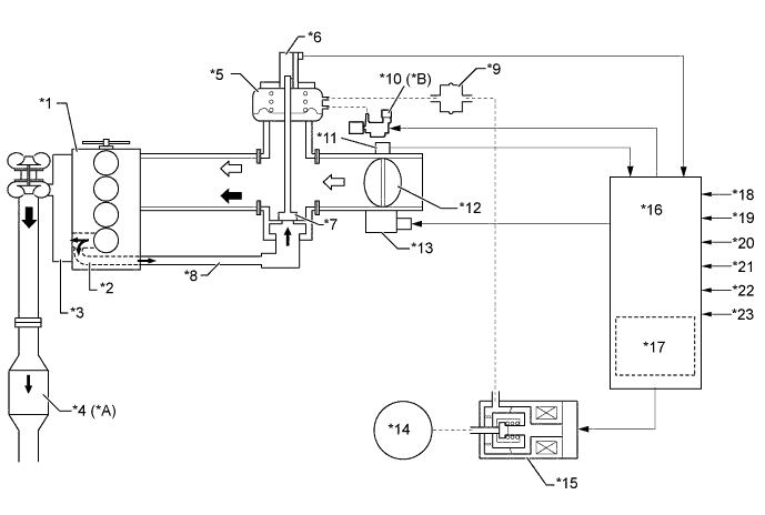
Text in Illustration (Models Compliant with EURO 2 Emission Regulations:) *A Models with 2KD-FTV Engine and Models with Variable Nozzle Vane Type Turbocharger and KUN15R-CRMSHN *B Models with Variable Nozzle Vane Type Turbocharger *1 Engine *2 EGR Passage in Cylinder Head *3 Exhaust Manifold *4 Oxidation Catalyst *5 Electric EGR Control Valve Assembly *6 EGR Valve Position Sensor *7 EGR Valve *8 EGR Pipe Sub-assembly *9 Vacuum Damper *10 VSV (for EGR Valve Close) *11 Throttle Position Sensor *12 Diesel Throttle Valve *13 Throttle Control Motor *14 Vacuum Pump *15 E-VRV (for EGR Valve Control) *16 ECM *17 Atmospheric Pressure Sensor *18 Crank Position Sensor *19 Accelerator Pedal Position Sensor *20 Engine Coolant Temperature Sensor *21 Turbo Pressure Sensor *22 Intake Air Temperature Sensor *23 Intake Mass Air Flow Meter Sub-assembly - - Exhaust Gas Intake Air
-
-
-
Catalyst Support Control (Models Compliant with EURO 5 Emission Regulations)
-
If the DPF catalyst temperature is high under normal driving conditions, PM captured by the DPF catalyst is oxidized by the temperature of the DPF catalyst and is emitted as CO2and H2O.
-
If the DPF catalyst temperature becomes low, catalyst performance decreases, resulting in an increase of the amount of PM stuck in the filter substrate. The ECM detects that the filter substrate is clogged by calculating the accumulated volume of the PM discharged by the engine. To reduce PM, the ECM controls the injection timing and the injection frequency of the injectors, and activates the exhaust fuel addition injector. At the same time, ECM controls the engine speed and glow plug assembly temperature via the glow plug controller.
As a result, filter substrate temperature becomes high and PM reacts with active oxygen and changes into CO2for purification. This is known as catalyst support control.
-
When PM has accumulated in the DPF catalyst while driving normally, the ECM automatically performs catalyst support control.
-
However, sufficient purification of the PM by the catalyst support control may not be possible when driving repeatedly over short distances. As a result, the PM accumulation limit may be surpassed. If a predetermined level of PM accumulation has been surpassed, the DPF indicator in the combination meter is illuminated. This prompts the driver to drive at a constant speed (60 km/h or more) for automatic catalyst support control to be carried out.
-
In addition, if the driver keeps driving without driving at a constant speed (60 km/h or more), the DPF indicator blinks when a predetermined level of PM accumulation is surpassed. This prompts the driver to bring the vehicle to a dealer for manual catalyst support control to be carried out.
-
Moreover, if the driver keeps driving without bringing the vehicle to a dealer, PM accumulates further. In this situation, if the catalyst support control is conducted, the DPF catalyst could be destroyed. To prevent this, the MIL will be illuminated when a predetermined driving distance is reached. At the same time, the ECM changes the engine control to the fail-safe mode, thus controlling the amount of fuel injection to a minimum.
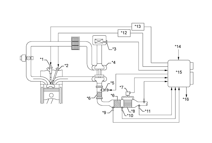
Text in Illustration *1 Injector Assembly *2 Glow Plug Assembly *3 Intake Mass Air Flow Meter Sub-assembly *4 Turbocharger Sub-assembly *5 Exhaust Fuel Addition Injector Assembly *6 Oxidation Catalyst *7 Differential Pressure Sensor *8 Diesel Particulate Filter (DPF) Catalyst *9 Exhaust Gas Temperature Sensor (Before Oxidation Catalyst) *10 Exhaust Gas Temperature Sensor (Before DPF Catalyst) *11 Exhaust Gas Temperature Sensor (After DPF Catalyst) *12 Glow Plug Controller *13 Injector Driver *14 Engine Coolant Temperature Sensor *15 ECM *16 Combination Meter Assembly 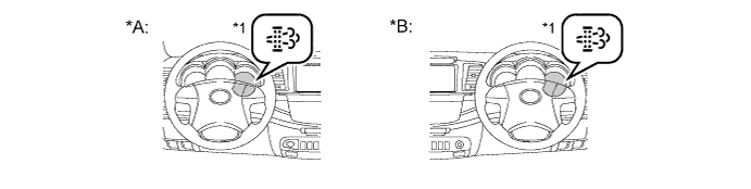
Text in Illustration *A LHD Models *B RHD Models *1 DPF Indicator - - Tech Tips
-
When replacing the front exhaust pipe with a new one, it is necessary to perform initialization of the DPF catalyst deteriorate data history in the ECM by using an intelligent tester II.
-
When replacing the ECM with a new one, it is necessary to read DPF catalyst deteriorate data history from the installed ECM and then transfer that data history to the new ECM by using an intelligent tester II. When the DPF catalyst deteriorate data history is not transferred, Diagnostic Trouble Code (DTC) P1601 is stored in the ECM, and the MIL comes on.
-
When replacing both the front exhaust pipe and the ECM, it is necessary to perform initialization of the DPF catalyst deteriorate data history in the ECM using an intelligent tester II. When DPF catalyst deteriorate history initialization is not performed, DTC P1601 is stored in the ECM and the MIL comes on.
-
A DPF switch for the manual catalyst support control is provided as optional equipment. The manual catalyst support control methods differ with provision of the DPF switch. For details of catalyst support control, refer to the corresponding Repair Manual.
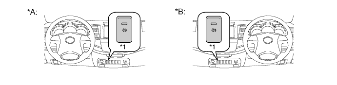
Text in Illustration *A LHD Models *B RHD Models *1 DPF Switch (Optional Equipment) - -
-
-
-