CYLINDER BLOCK INSPECTION
PROCEDURE
-
INSPECT CYLINDER BLOCK FOR WARPAGE
-
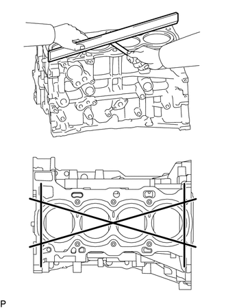
Using a precision straightedge and feeler gauge, measure the warpage of the surface which contacts the cylinder head gasket.
Maximum Warpage 0.05 mm (0.00197 in.) If the warpage is more than the maximum, replace the cylinder block sub-assembly.
-
-
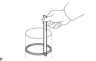
INSPECT CYLINDER BORE
-
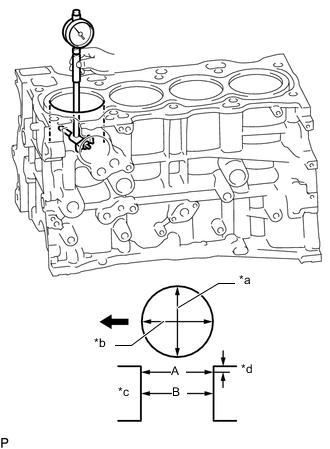
*a Thrust Direction *b Axial Direction *c Center *d 10 mm (0.394 in.) 
Front of Engine Using a cylinder gauge, measure the cylinder bore diameter at the positions (A) and (B) in the thrust and axial directions.
Reference Diameter (New Parts) 86.000 to 86.013 mm (3.38582 to 3.38633 in.) Maximum Diameter 86.13 mm (3.39094 in.) If the average diameter of the 4 positions is more than the maximum, replace the cylinder block sub-assembly.
-
-
INSPECT PISTON
-
Using a gasket scraper, remove any carbon from the piston top.
-
Using a groove cleaning tool or a broken ring, clean the piston ring grooves.
-
Using a brush and solvent, thoroughly clean the piston.
Note
Do not use a wire brush.
-
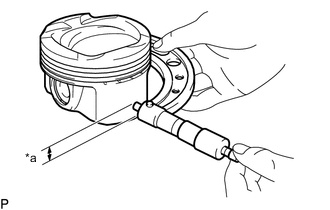
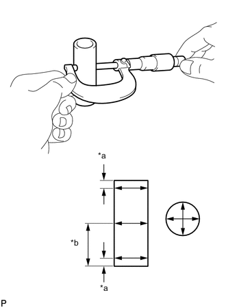
*a Distance Using a micrometer, measure the piston diameter at a right angle to the position center line where the distance from the bottom of the piston is as specified.
Distance 10.5 mm (0.413 in.) Reference Diameter (New Parts) 85.960 to 85.972 mm (3.38425 to 3.38472 in.)
-
-
INSPECT PISTON OIL CLEARANCE
-
Measure the cylinder bore diameter in the thrust direction.
-
Subtract the piston diameter measurement from the cylinder bore diameter measurement.
Reference Oil Clearance (New Parts) 0.030 to 0.053 mm (0.00118 to 0.00209 in.) Maximum Oil Clearance 0.10 mm (0.00394 in.) If the oil clearance is more than the maximum, replace all the pistons. If necessary, replace the cylinder block sub-assembly.
-
-
INSPECT RING GROOVE CLEARANCE
-
Using a feeler gauge, measure the clearance between a new piston ring set and the wall of the ring groove.
Standard Ring Groove Clearance Item Specified Condition No. 1 Compression Ring 0.020 to 0.060 mm (0.000787 to 0.00236 in.) No. 2 Compression Ring 0.020 to 0.070 mm (0.000787 to 0.00276 in.) Oil Ring Expander 0.070 to 0.150 mm (0.00276 to 0.00591 in.) If the ring groove clearance is not as specified, replace the piston with piston pin.
-
-
INSPECT PISTON RING END GAP
-
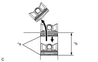
*a Piston Ring *b 120 mm (4.72 in.) Insert the piston ring into the cylinder bore.
-
Using a piston, push the piston ring a little beyond the bottom of the ring travel, 120 mm (4.72 in.) from the top of the cylinder block sub-assembly.
-
Using a feeler gauge, measure the end gap.
Standard End Gap Item Specified Condition No. 1 Compression Ring 0.18 to 0.25 mm (0.00709 to 0.00984 in.) No. 2 Compression Ring 0.65 to 0.75 mm (0.0256 to 0.0295 in.) Oil Ring (Side Rail) 0.10 to 0.35 mm (0.00394 to 0.0138 in.) Maximum End Gap Item Specified Condition No. 1 Compression Ring 0.85 mm (0.0335 in.) No. 2 Compression Ring 1.35 mm (0.0531 in.) Side Rail 0.95 mm (0.0374 in.) If the end gap is more than the maximum, replace the piston ring set. If the end gap is more than the maximum even with a new piston ring set, replace the cylinder block sub-assembly.
-
-
INSPECT PISTON PIN OIL CLEARANCE
-
Confirm each mark on the piston, piston pin and connecting rod sub-assembly.
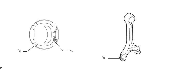
*a Front Mark *b Position Pin Hole Inside Diameter Mark *c Connecting Rod Small End Bush Inside Diameter Mark - - -
Using a caliper gauge, measure the inside diameter of the piston pin hole.
Standard Piston Pin Hole Inside Diameter Item Specified Condition Mark A 24.001 to 24.004 mm (0.94492 to 0.94504 in.) Mark B 24.005 to 24.007 mm (0.94508 to 0.94516 in.) Mark C 24.008 to 24.010 mm (0.94519 to 0.94527 in.) -
*a 5 mm (0.197 in.) *b 28 mm (1.10 in.) Using a micrometer, measure the piston pin diameter.
Standard Piston Pin Diameter Item Specified Condition Mark A 23.997 to 24.000 mm (0.94476 to 0.94488 in.) Mark B 24.001 to 24.003 mm (0.94492 to 0.94500 in.) Mark C 24.004 to 24.006 mm (0.94504 to 0.94512 in.) If the diameter is not as specified, replace the piston pin.
-
Using a caliper gauge, measure the inside diameter of the connecting rod small end bush.
Standard Connecting Rod Small End Bush Inside Diameter Item Specified Condition Mark A 24.005 to 24.008 mm (0.94508 to 0.94519 in.) Mark B 24.009 to 24.011 mm (0.94523 to 0.94531 in.) Mark C 24.012 to 24.014 mm (0.94535 to 0.94543 in.) If the diameter is not as specified, replace the connecting rod sub-assembly.
-
Subtract the piston pin diameter measurement from the piston pin hole inside diameter measurement.
Standard Oil Clearance 0.001 to 0.007 mm (0.0000394 to 0.000276 in.) Maximum Oil Clearance 0.013 mm (0.000512 in.) If the oil clearance is more than the maximum, replace the piston and piston pin as a set.
-
Subtract the piston pin diameter measurement from the connecting rod small end bush inside diameter measurement.
Standard Oil Clearance 0.005 to 0.011 mm (0.000197 to 0.000433 in.) Maximum Oil Clearance 0.017 mm (0.000669 in.) If the oil clearance is more than the maximum, replace the connecting rod sub-assembly. If necessary, replace the connecting rod sub-assembly and piston pin as a set.
-
-
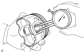
INSPECT CONNECTING ROD SUB-ASSEMBLY
-
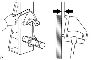
Using a connecting rod aligner and feeler gauge, check the connecting rod sub-assembly alignment.
-
Check for misalignment.
Maximum Misalignment 0.05 mm (0.00197 in.) per 100 mm (3.94 in.) If the misalignment is more than the maximum, replace the connecting rod sub-assembly.
-
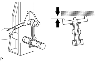
Check for twist.
Maximum Twist 0.15 mm (0.00591 in.) per 100 mm (3.94 in.) If the twist is more than the maximum, replace the connecting rod sub-assembly.
-
-
-
INSPECT CRANKSHAFT
-
Inspect for runout.
-
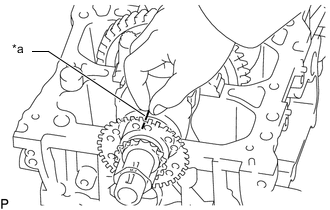
Using a dial indicator and V-blocks, measure the runout as shown in the illustration.
Maximum Runout 0.03 mm (0.00118 in.) If the runout is more than the maximum, replace the crankshaft.
-
-
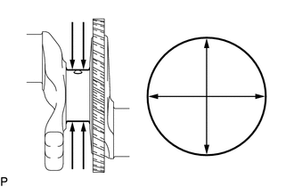
Inspect the main journals.
-
Using a micrometer, measure the diameter of each main journal.
Standard Main Journal Diameter 54.988 to 55.000 mm (2.16488 to 2.16535 in.) If the diameter is not as specified, check the crankshaft oil clearance. If necessary, replace the crankshaft.
-
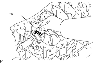
Check each main journal for taper and out-of-round as shown in the illustration.
Maximum Taper and Out-of-round 0.003 mm (0.000118 in.) If the taper or out-of-round is more than the maximum, replace the crankshaft.
-
-
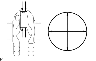
Inspect the crank pin.
-
Using a micrometer, measure the diameter of each crank pin.
Standard Crank Pin Diameter 51.492 to 51.500 mm (2.02724 to 2.02756 in.) If the diameter is not as specified, check the connecting rod oil clearance. If necessary, replace the crankshaft.
-
Inspect each crank pin for taper and out-of-round as shown in the illustration.
Maximum Taper and Out-of-round 0.003 mm (0.000118 in.) If the taper or out-of-round is more than the maximum, replace the crankshaft.
-
-
-
INSPECT CRANKSHAFT OIL CLEARANCE
-
Install the crankshaft bearings.
-
Install the crankshaft thrust washers.
-
*a Plastigage Clean each main journal and crankshaft bearing.
-
Place the crankshaft on the cylinder block sub-assembly.
-
Lay a strip of Plastigage across each journal.
-
Install the crankshaft bearing caps.
Note
Do not turn the crankshaft.
-
Remove the crankshaft bearing caps.
-
*a Plastigage Measure the Plastigage at its widest point.
Standard Oil Clearance 0.018 to 0.042 mm (0.000709 to 0.00165 in.) Maximum Oil Clearance 0.050 mm (0.00197 in.) Note
Remove the Plastigage completely after the measurement.
If the oil clearance is more than the maximum, replace the crankshaft bearing. If necessary, replace the crankshaft.
-
Perform the inspection above for each journal.
-
-
INSPECT CRANKSHAFT BEARING CAP BOLT
-
Type A:
-
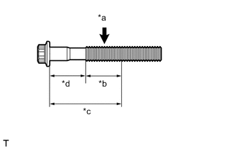
*a Measuring Point *b Measuring Area *c 59 mm (2.32 in.) *d 45 mm (1.77 in.) Using a vernier caliper, measure the diameter of the tension portion of the crankshaft bearing cap bolts.
Measuring Point 45 to 59 mm (1.77 to 2.32 in.) Standard Diameter 10.8 to 11.0 mm (0.425 to 0.433 in.) Minimum Diameter 10.7 mm (0.421 in.) Tech Tips
Diameter measurements should be done at several points.
If the diameter is less than the minimum, replace the crankshaft bearing cap bolt.
-
-
Type B:
-
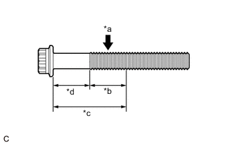
*a Measuring Point *b Measuring Area *c 59 mm (2.32 in.) *d 45 mm (1.77 in.) Using a vernier caliper, measure the diameter of the tension portion of the crankshaft bearing cap bolts.
Measuring Point 45 to 59 mm (1.77 to 2.32 in.) Standard Diameter 10.8 to 11.0 mm (0.425 to 0.433 in.) Minimum Diameter 10.7 mm (0.421 in.) Tech Tips
Diameter measurements should be done at several points.
If the diameter is less than the minimum, replace the crankshaft bearing cap bolt.
-
-
-
INSPECT CONNECTING ROD BOLT
-
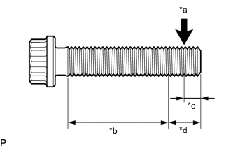
*a Measurement Point (A) *b Measurement Area (B) *c 5.0 mm (0.197 in.) *d 10 mm (0.394 in.) Using a vernier caliper, measure the diameter of the threads at the measurement point (A).
Standard Diameter 8.86 to 9.00 mm (0.349 to 0.354 in.) Tech Tips
If there is any thread deformation, replace the connecting rod bolt with a new one.
-
Using a vernier caliper, measure the diameter of the threads at several points within the measurement area (B) shown in the illustration.
Tech Tips
-
Diameter measurements should be done at several points.
-
If there is any thread deformation, replace the connecting rod bolt with a new one.
-
-
Calculate the difference between the measurement (A) and the measurement of (B).
Difference between (A) and (B) 0.15 mm (0.00591 in.) or less Tech Tips
-
If there is any thread deformation, replace the connecting rod bolt with a new one.
-
-