CAMSHAFT INSTALLATION

CAUTION / NOTICE / HINT
Tech Tips
Perform "Inspection After Repair" after replacing the camshaft, No. 2 camshaft, camshaft timing gear assembly or camshaft timing exhaust gear assembly.
-
for Rear Air Fuel Ratio Sensor:
-
for Rear Heated Oxygen Sensor:
PROCEDURE
-
INSTALL NO. 2 CAMSHAFT BEARING
-
INSTALL NO. 1 CAMSHAFT BEARING
-
INSTALL OIL CONTROL VALVE FILTER
-
INSTALL CAMSHAFT TIMING EXHAUST GEAR ASSEMBLY
-
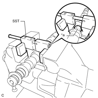
*a Hexagonal Portion Using SST, grip the hexagonal portion, and then secure the SST and No. 2 camshaft in a vise as shown in the illustration.
- SST
- 09212-31010
Note
-
Do not damage the No. 2 camshaft.
-
Never grip areas other than the hexagonal portion, as this may cause damage.
-
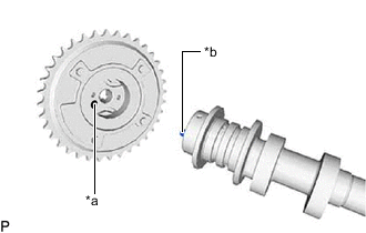
*a Knock Pin Hole *b Knock Pin Align the knock pin of the No. 2 camshaft with the knock pin hole of the camshaft timing exhaust gear assembly and fit the camshaft timing exhaust gear assembly to the No. 2 camshaft.
-
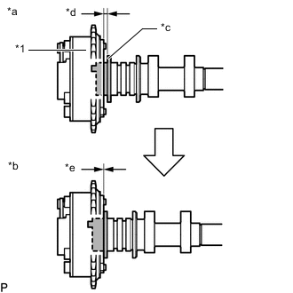
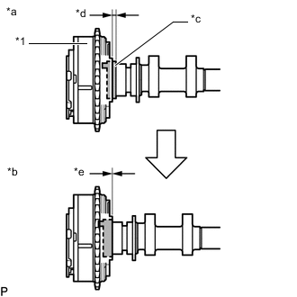
*1 Camshaft Timing Exhaust Gear Assembly *a Incorrect *b Correct *c No. 2 Camshaft Flange *d Gap *e No Gap Check that there is no gap between the camshaft timing exhaust gear assembly and No. 2 camshaft flange.
-
While securely holding the No. 2 camshaft, install the bolt of the camshaft timing exhaust gear assembly by hand.
-
Tighten the bolt.
- Torque:
- 85 N*m { 867 kgf*cm, 63 ft.*lbf }
Tech Tips
Perform "Inspection After Repair" after replacing the camshaft timing exhaust gear assembly.
-
for Rear Air Fuel Ratio Sensor:
-
for Rear Heated Oxygen Sensor:
-
-
SET NO. 1 CYLINDER TO TDC/COMPRESSION
-
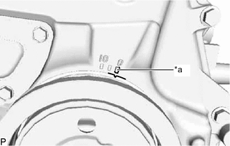
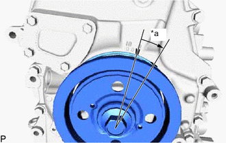
*a Timing Notch (Groove) Turn the crankshaft pulley until its timing notch (groove) and the timing mark "0" of the timing chain cover assembly are aligned.
-
-
INSTALL NO. 2 CAMSHAFT
-
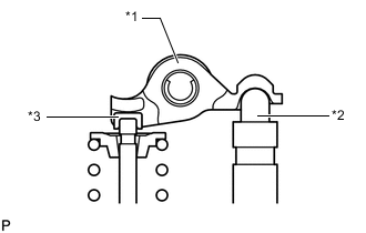
*1 No. 1 Valve Rocker Arm Sub-assembly *2 Valve Lash Adjuster Assembly *3 Valve Stem Cap Check that the No. 1 valve rocker arm sub-assemblies are installed as shown in the illustration.
-
Apply a light coat of engine oil to the No. 2 camshaft journals and camshaft housing sub-assembly.
-
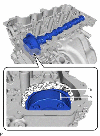
*a Paint Mark *b Timing Mark Align the paint mark of the chain sub-assembly and the timing mark of the camshaft timing exhaust gear assembly. Then install the No. 2 camshaft and camshaft timing exhaust gear assembly.
-
-
INSTALL CAMSHAFT TIMING GEAR ASSEMBLY
-
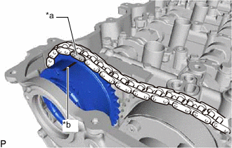
*a Paint Mark *b Timing Mark Align the paint mark of the chain sub-assembly and the timing mark of the camshaft timing gear assembly. Then install the camshaft timing gear assembly.
-
-
INSTALL CAMSHAFT
-
*1 No. 1 Valve Rocker Arm Sub-assembly *2 Valve Lash Adjuster Assembly *3 Valve Stem Cap Check that the No. 1 valve rocker arm sub-assemblies are installed as shown in the illustration.
-
Apply a light coat of engine oil to the camshaft journals and camshaft housing sub-assembly.
-
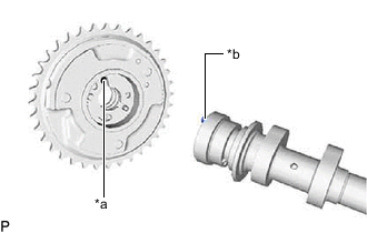
*a Knock Pin Hole *b Knock Pin Align the knock pin of the camshaft with the knock pin hole of the camshaft timing gear assembly and fit the camshaft timing gear assembly to the camshaft.
-
*1 Camshaft Timing Gear Assembly *a Incorrect *b Correct *c Camshaft Flange *d Gap *e No Gap Check that there is no gap between the camshaft timing gear assembly and camshaft flange.
-
-
TEMPORARILY INSTALL CAMSHAFT TIMING GEAR BOLT
Note
There are several different types of camshaft timing gear bolt. Make sure to check the identification mark to determine the tightening torque.
Identification Mark Item Identification Mark Type A A Type B C 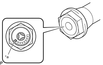
*a Identification Mark
-
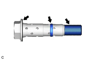
Apply engine oil to the areas of the camshaft timing gear bolt shown in the illustration.
-
Temporarily install the camshaft timing gear bolt.
Tech Tips
Temporarily install the camshaft timing gear bolt until 2 or 3 threads are screwed into the camshaft.
-
-
INSTALL CAMSHAFT BEARING CAP
-
Place the No. 1 camshaft bearing cap, No. 2 camshaft bearing cap, No. 3 camshaft bearing cap and No. 4 camshaft bearing cap in their correct positions.
-
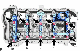
Uniformly tighten the 10 bolts in several steps in the order shown in the illustration.
- Torque:
- 27 N*m { 275 kgf*cm, 20 ft.*lbf }
-
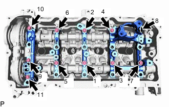
Uniformly tighten the 11 bolts in several steps in the order shown in the illustration.
- Torque:
- 16 N*m { 163 kgf*cm, 12 ft.*lbf }
-
Check the torque of each bolt again.
-
-
TIGHTEN CAMSHAFT TIMING GEAR BOLT
-
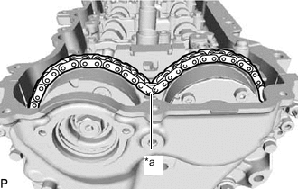
*a Slack Check that there is some slack in the chain sub-assembly as shown in the illustration.
-
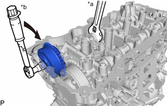
*a Hold *b Turn Use a wrench to hold the hexagonal portion of the camshaft, tighten the camshaft timing gear bolt.
- Torque:
- Type A
- 120 N*m { 1224 kgf*cm, 89 ft.*lbf }
- Type B
- 95 N*m { 969 kgf*cm, 70 ft.*lbf }
Note
Be careful not to damage the cylinder head sub-assembly or spark plug tube with the wrench.
-
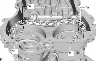
*a Paint Mark *b Timing Mark Check that each timing mark of the camshaft timing gear assembly and camshaft timing exhaust gear assembly is aligned with each paint mark as shown in the illustration.
-
-
ADD ENGINE OIL
-
INSTALL CAMSHAFT TIMING OIL CONTROL SOLENOID ASSEMBLY
-
INSTALL TIMING CHAIN GUIDE
-
INSTALL NO. 1 CHAIN TENSIONER ASSEMBLY
-
*a Approximately 15° Turn the crankshaft pulley approximately 15° clockwise.
-
Install a new gasket and the No. 1 chain tensioner assembly with the nut and bolt.
- Torque:
- 10 N*m { 102 kgf*cm, 7 ft.*lbf }
Note
Be careful not to drop the gasket into the timing chain cover assembly.
-
Remove the pin from the stopper plate.
-
-
SET NO. 1 CYLINDER TO TDC/COMPRESSION
-
Turn the crankshaft pulley until the timing notch (groove) and the timing mark "0" of the timing chain cover assembly are aligned.
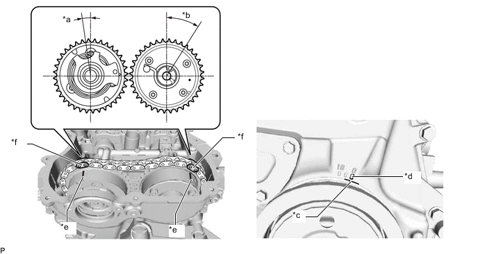
*a Approximately 7° *b Approximately 32° *c Timing Notch (Groove) *d Timing Mark "0" *e Timing Mark *f Paint Mark -
Check that each timing mark of the camshaft timing gear assembly and camshaft timing exhaust gear assembly is aligned with each paint mark as shown in the illustration.
-
-
INSTALL TIMING CHAIN COVER PLATE
-
INSTALL VACUUM PUMP ASSEMBLY
-
CONNECT NO. 2 VACUUM TRANSMITTING HOSE ASSEMBLY
-
INSTALL CYLINDER HEAD COVER SUB-ASSEMBLY
-
INSTALL FUEL PUMP ASSEMBLY (for High Pressure)
-
CONNECT ENGINE WIRE
-
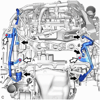

Connector 
Bolt Connect the engine wire with the 3 bolts.
- Torque:
- Bolt (A)
- 8.0 N*m { 82 kgf*cm, 71 in.*lbf }
- Bolt (B)
- 8.4 N*m { 86 kgf*cm, 74 in.*lbf }
-
Connect the 5 connectors.
-
-
INSTALL IGNITION COIL ASSEMBLY
-
INSTALL V-RIBBED BELT
-
INSTALL ENGINE HANGERS
-
INSTALL ENGINE FROM ENGINE STAND