ENGINE IMMOBILISER SYSTEM(w/ Entry and Start System) Security Indicator Light Does not Blink
DESCRIPTION
-
When the engine immobiliser system is set, the security indicator light blinks continuously, but does not illuminate if the engine immobiliser system is not set.
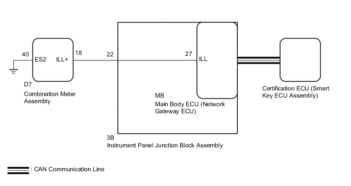
WIRING DIAGRAM
CAUTION / NOTICE / HINT
Note
Before replacing the certification ECU (smart key ECU assembly), refer to the Service Bulletin.
PROCEDURE
-
CHECK FOR DTC
-
Check for DTCs Click here.
OK DTC is not output.
NG 
GO TO DTC CHART Click here
OK 
-
-
READ VALUE USING GTS (IMMOBILISER)
-
Using the GTS, read the Data List Click here.
Entry&Start Tester Display Measurement Item/Range Normal Condition Diagnostic Note Immobiliser Engine immobiliser system status determined by certification ECU (smart key ECU assembly) / Set or Unset Set: Engine immobiliser set (engine start prohibited) (engine switch off)
Unset: Engine immobiliser unset (engine start permitted) [engine switch on (ACC) or on (IG)]
When the engine immobiliser system does not change to the unset state, this item can be used to determine if the cause is the certification ECU (smart key ECU assembly). OK "Set" appears on screen.
NG
REPLACE CERTIFICATION ECU (SMART KEY ECU ASSEMBLY)
OK
-
-
PERFORM ACTIVE TEST USING GTS (SECURITY INDICATOR)
-
Check that the security indicator light illuminates when operating it with the Active Test Click here.
Main Body Tester Display Test Part Control Range Diagnostic Note Security Indicator Security indicator light ON/OFF - OK Security indicator light can be turned on and off using GTS.
OK
REPLACE MAIN BODY ECU (NETWORK GATEWAY ECU) Click here
NG
-
-
CHECK HARNESS AND CONNECTOR (INSTRUMENT PANEL JUNCTION BLOCK - COMBINATION METER ASSEMBLY)
-
Disconnect the 3B instrument panel junction block assembly connector.
-
Disconnect the D7 combination meter assembly connector.
-
Measure the resistance according to the value(s) in the table below.
Standard Resistance Tester Connection Condition Specified Condition 3B-22 - D7-18 Always Below 1 Ω D7-40 - Body ground Always Below 1 Ω 3B-22 - Body ground Always 10 kΩ or higher
NG
REPAIR OR REPLACE HARNESS OR CONNECTOR
OK
-
-
INSPECT INSTRUMENT PANEL JUNCTION BLOCK ASSEMBLY
-
Remove the instrument panel junction block assembly Click here.
-
Remove the main body ECU (network gateway ECU) from the instrument panel junction block assembly.
-
Measure the resistance according to the value(s) in the table below.
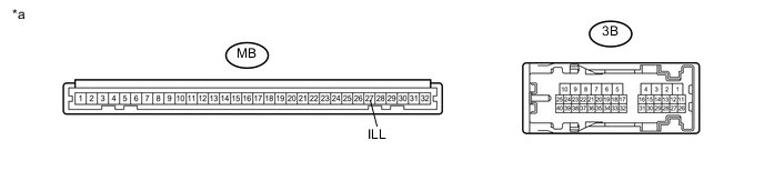
Text in Illustration *a Component without harness connected
(Instrument Panel Junction Block Assembly)
- - Standard Resistance Tester Connection Condition Specified Condition MB-27 (ILL) - 3B-22 Always Below 1 Ω
NG
REPLACE INSTRUMENT PANEL JUNCTION BLOCK ASSEMBLY Click here
OK
-
-
REPLACE COMBINATION METER ASSEMBLY
-
Replace the combination meter assembly with a new one Click here.
-
When the immobiliser is set, check that the security indicator light blinks.
OK Security indicator light blinks.
OK
END
NG
REPLACE MAIN BODY ECU (NETWORK GATEWAY ECU) Click here
-