REAR DOOR LOCK REMOVAL
CAUTION / NOTICE / HINT
The necessary procedures (adjustment, calibration, initialization, or registration) that must be performed after parts are removed, installed, or replaced during the rear door lock with motor assembly removal/installation are shown below.
| Replacement Part or Procedure | Necessary Procedures | Effect/Inoperative Function when Necessary Procedure not Performed | Link |
|---|---|---|---|
| Disconnect cable from negative battery terminal | Memorize steering angle neutral point | Lane departure alert system (w/ Steering Control) | |
| Simple intelligent parking assist system*1 | |||
| Toyota parking assist-sensor system (w/ Simple Intelligent Parking Assist System)*1 | |||
| Pre-collision system | |||
| Initialize back door lock | Power door lock control system | ||
| Drive the vehicle until stop and start control is permitted (approximately 5 to 60 minutes)*2 | Stop and start system | ||
|
Initialize Power Window Control System |
|
*1: When performing learning using the GTS.
*2: w/ Stop and start system
Tech Tips
-
Use the same procedure for the RH side and LH side.
-
The following procedure is for the LH side.
PROCEDURE
-
PRECAUTION
Note
After turning the ignition switch off, waiting time may be required before disconnecting the cable from the negative (-) battery terminal. Therefore, make sure to read the disconnecting the cable from the negative (-) battery terminal notices before proceeding with work.
-
DISCONNECT CABLE FROM NEGATIVE BATTERY TERMINAL
-
for 8NR-FTS:
-
for 3ZR-FAE:
Note
When disconnecting the cable, some systems need to be initialized after the cable is reconnected.
-
-
REMOVE REAR DOOR REAR FRAME BRACKET
-
REMOVE REAR DOOR INSIDE HANDLE BEZEL PLUG
-
REMOVE REAR POWER WINDOW REGULATOR SWITCH ASSEMBLY WITH REAR DOOR ARMREST BASE UPPER PANEL
-
REMOVE REAR DOOR TRIM BOARD SUB-ASSEMBLY
-
REMOVE REAR DOOR TRIM BRACKET
-
REMOVE REAR DOOR SERVICE HOLE COVER
-
REMOVE REAR DOOR OUTSIDE HANDLE ASSEMBLY
-
REMOVE REAR DOOR OUTSIDE HANDLE COVER
-
REMOVE REAR DOOR LOCK WITH MOTOR ASSEMBLY
-
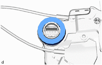
Disconnect the connector.
-
Using a T30 "TORX" socket wrench, remove the 3 screws and rear door lock with motor assembly.
-
When reusing the rear door lock with motor assembly:
-
Remove the door lock wiring harness seal from the rear door lock with motor assembly.
-
-
-
REMOVE REAR DOOR LOCK REMOTE CONTROL CABLE ASSEMBLY
-
w/o Double Locking System:
-
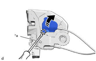
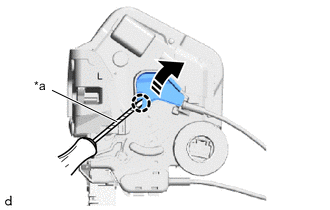
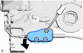
*a Protective Tape 
Remove in this Direction Using a screwdriver with its tip wrapped in protective tape, disengage the claw as shown in the illustration.
-
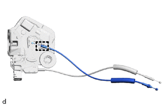
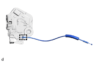
Disengage the guide to remove the rear door lock remote control cable assembly from the rear door lock with motor assembly.
-
-
w/ Double Locking System:
-
*a Protective Tape Remove in this Direction Using a screwdriver with its tip wrapped in protective tape, disengage the claw as shown in the illustration.
-
Disengage the guide to remove the rear door lock remote control cable assembly from the rear door lock with motor assembly.
-
-
-
REMOVE REAR DOOR INSIDE LOCKING CABLE ASSEMBLY
-
w/o Double Locking System:
-
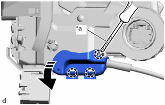
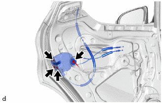
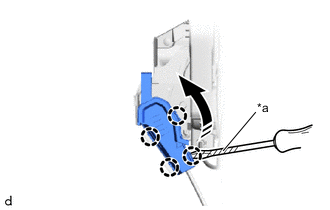
*a Protective Tape Remove in this Direction Using a screwdriver with its tip wrapped in protective tape, disengage the claws as shown in the illustration.
-
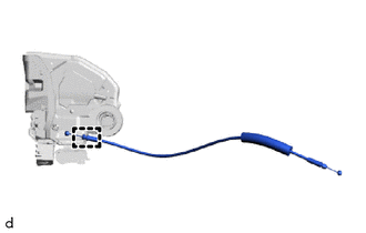
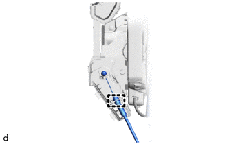
Disengage the guide to remove the rear door inside locking cable assembly from the rear door lock with motor assembly.
-
-
w/ Double Locking System:
-
*a Protective Tape Remove in this Direction Using a screwdriver with its tip wrapped in protective tape, disengage the claws as shown in the illustration.
-
Disengage the guide to remove the rear door inside locking cable assembly from the rear door lock with motor assembly.
-
-
-
REMOVE NO. 1 REAR DOOR LOCK REMOTE CONTROL CABLE ASSEMBLY
-
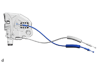
*a Protective Tape Remove in this Direction Using a screwdriver with its tip wrapped in protective tape, disengage the claws as shown in the illustration.
-
Disengage the guide to remove the No. 1 rear door lock remote control cable assembly from the rear door lock with motor assembly.
-