ENGINE UNIT INSTALLATION

PROCEDURE
-
INSTALL NO. 8 ENGINE WIRE
-
INSTALL V-RIBBED BELT TENSIONER ASSEMBLY
-
INSTALL IDLER PULLEY SUB-ASSEMBLY
-
INSTALL OIL FILLER CAP GASKET
-
Install the oil filler cap gasket to the oil filler cap sub-assembly.
-
-
INSTALL OIL FILLER CAP SUB-ASSEMBLY
-
Install the oil filler cap sub-assembly to the cylinder head cover sub-assembly.
-
-
INSTALL WIRE HARNESS CLAMP BRACKET
-
for Engine Upper Side:
Install the 2 wire harness clamp brackets with the 2 bolts to the cylinder head cover sub-assembly.
- Torque:
- 8.0 N*m { 82 kgf*cm, 71 in.*lbf }
-
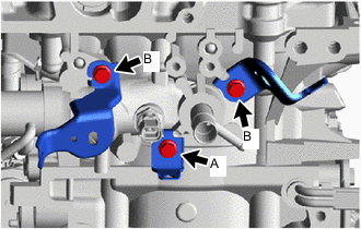
for Engine Rear Side:
Install the 3 wire harness clamp brackets with the 3 bolts to the cylinder head sub-assembly.
- Torque:
- for bolt A
- 8.0 N*m { 82 kgf*cm, 71 in.*lbf }
- for bolt B
- 12.5 N*m { 127 kgf*cm, 9 ft.*lbf }
-
-
INSTALL ENGINE WIRE
-
INSTALL TURBOCHARGER SUB-ASSEMBLY
-
CONNECT TURBO OIL INLET PIPE SUB-ASSEMBLY
-
INSTALL EXHAUST MANIFOLD CONVERTER SUB-ASSEMBLY
-
INSTALL NO. 2 EXHAUST MANIFOLD HEAT INSULATOR
-
INSTALL NO. 1 EXHAUST MANIFOLD HEAT INSULATOR
-
INSTALL IGNITION COIL ASSEMBLY
-
INSTALL INTAKE MANIFOLD WITH INTERCOOLER ASSEMBLY AND THROTTLE WITH MOTOR BODY ASSEMBLY
-
Install the 2 new No. 1 intake manifold to head gaskets to the intake manifold.
-
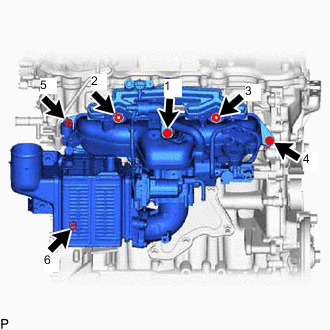
Temporarily install the intake manifold with intercooler assembly and throttle with motor body assembly with the 4 bolts and 2 nuts.
-
Tighten the 4 bolts and 2 nuts in the sequence shown in the illustration to install the intake manifold with intercooler assembly and throttle with motor body assembly.
- Torque:
- 21 N*m { 214 kgf*cm, 15 ft.*lbf }
-
-
INSTALL NO. 2 PCV HOSE
-
CONNECT NO. 1 AND NO. 2 WATER BY-PASS HOSE
-
Connect the No. 1 water by-pass hose to the cylinder head sub-assembly, and slide the clamp to secure the hose.
-
Connect the No. 2 water by-pass hose to the No. 1 water by-pass pipe, and slide the clamp to secure the hose.
-
-
CONNECT VACUUM TRANSMITTING HOSE ASSEMBLY
-
CONNECT NO. 2 VACUUM TRANSMITTING HOSE ASSEMBLY
-
INSTALL ENGINE WIRE
-
INSTALL PURGE VSV
-
INSTALL NO. 2 WATER BY-PASS PIPE
-
INSTALL NO. 1 COMPRESSOR MOUNTING BRACKET
-
Install the 2 stud bolts to the cylinder block sub-assembly and stiffening crankcase assembly.
- Torque:
- 9.0 N*m { 92 kgf*cm, 80 in.*lbf }
-
Install the No. 1 compressor mounting bracket with the 2 bolts and 2 nuts.
- Torque:
- 21 N*m { 214 kgf*cm, 15 ft.*lbf }
-
-
INSTALL COMPRESSOR ASSEMBLY WITH PULLEY
-
INSTALL GENERATOR ASSEMBLY
-
INSTALL FAN AND GENERATOR V BELT