REAR SHOCK ABSORBER REMOVAL

CAUTION / NOTICE / HINT
The necessary procedures (adjustment, calibration, initialization, or registration) that must be performed after parts are removed, installed, or replaced during the rear shock absorber removal/installation are shown below.
| Necessary Procedure After Parts Removed/Installed/Replaced | ||||||||||||||||||
|---|---|---|---|---|---|---|---|---|---|---|---|---|---|---|---|---|---|---|
|
Tech Tips
-
Use the same procedure for the RH and LH side.
-
The following procedure is for the LH side.
PROCEDURE
-
REMOVE PACKAGE TRAY TRIM GARNISH LH
-
REMOVE PACKAGE TRAY TRIM GARNISH RH
Tech Tips
Use the same procedure described for the LH side.
-
REMOVE NO. 1 CENTER SPEAKER GRILLE SUB-ASSEMEBLY
-
REMOVE PACKAGE TRAY TRIM SIDE COVER LH
-
REMOVE REAR WHEEL
-
REMOVE ROCKER PANEL MOULDING PROTECTOR LH
-
REMOVE REAR WHEEL HOUSE LINER LH
-
REMOVE REAR STABILIZER LINK ASSEMBLY LH
-
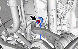
Remove the nut and rear stabilizer link assembly LH from the rear stabilizer bar.
Tech Tips
If the ball joint turns together with the nut, use a hexagon socket wrench 6 mm to hold the stud bolt.
-
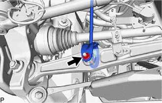
Remove the bolt, nut and rear stabilizer link assembly LH from the rear No. 2 suspension arm assembly LH.
-
-
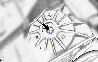
REMOVE REAR SHOCK ABSORBER CAP LH
-
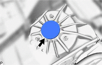
Remove the rear shock absorber cap LH.
-
-
REMOVE REAR SHOCK ABSORBER WITH COIL SPRING
-
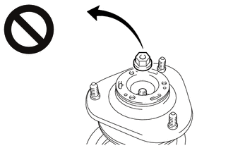
Loosen the lock nut.
CAUTION:
-
Only loosen the lock nut, do not remove it.
-
If the lock nut is removed with the rear coil spring under tension, components of the rear shock absorber with coil spring may fly off.
Note
If the rear shock absorber with coil spring will not be disassembled, do not loosen the lock nut.
Tech Tips
If the nut is hard to see, use a mirror.
-
-
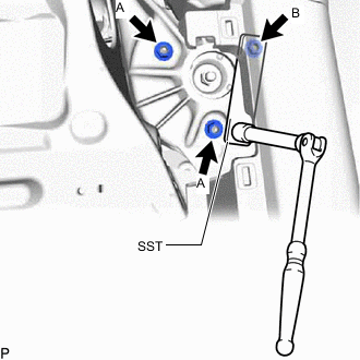
Using SST, remove the nut B.
- SST
- 09249-37010
Tech Tips
If the nut is hard to see, use a mirror.
-
Remove the 2 nuts A from the rear shock absorber with coil spring (upperside).
Tech Tips
If the nut is hard to see, use a mirror.
-
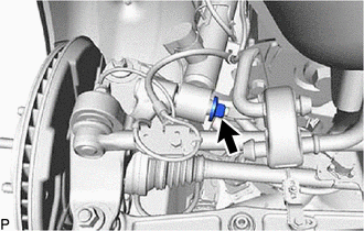
Remove the nut from the rear shock absorber with coil spring (lower side).
-
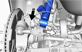

Remove in this Direction (1) 
Remove in this Direction (2) Remove the rear shock absorber with coil spring and washer as shown in the illustration.
-
-
REMOVE REAR SHOCK ABSORBER ASSEMBLY LH
-
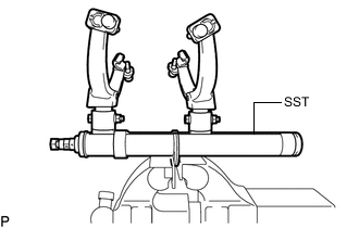
Secure SST in a vise.
- SST
- 09727-30022 ( 09727-00010, 09727-00022, 09727-00031 )
-
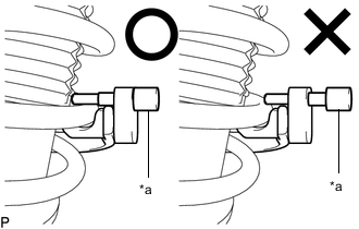
Attach the hooks of each SST arm across the diameter of the coil spring.
CAUTION:
-
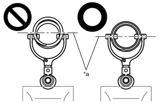
*a Rear Coil Spring Diameter Do not perform the work without checking to make sure that the claws of the hooks are securely engaged.
-
It could cause the hook to slip off and the spring to fly out, which could result in an injury.
-
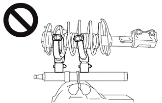
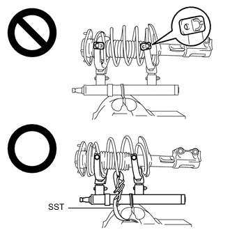
Do not install SST to the rear coil spring unless its top and bottom hook distance is set to the widest condition.
-
It could cause the hook to slip off and the spring to fly out, which could result in an injury.
-
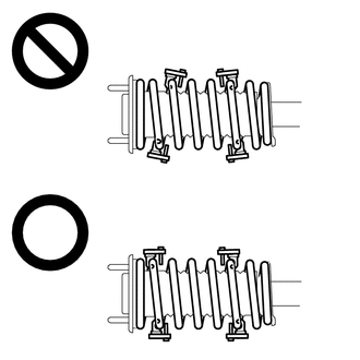
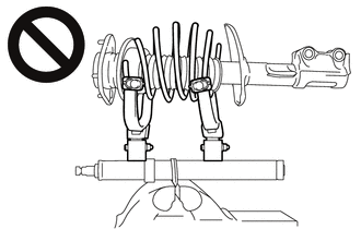
Do not install SST when the distances between the SST arms or the number of coils of the coil spring between the hooks are not the same.
-
It could cause the hook to slip off and the spring to fly out, which could result in an injury.
-
-
*a Stopper Pin Install the stopper pins to the hooks of SST.
CAUTION:
Do not perform the work if the stopper pin is not securely installed.
-
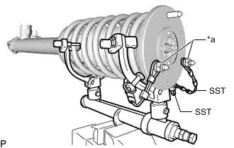
*a Vehicle Nut Install SST and 2 vehicle nuts to the upper support as shown in the illustration.
- SST
- 09727-30022 ( 09727-00090, 09727-00100 )
-
Using SST, compress the coil spring.
CAUTION:
-
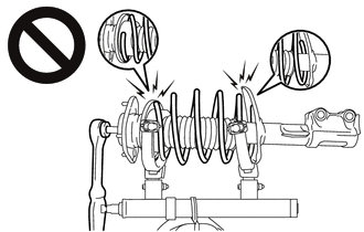
While compressing the spring, if the rear coil spring starts to bend into a bow shape, do not continue the work.
-
It could cause the hook to slip off and the spring to fly out, which could result in an injury.
-
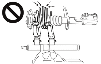
Do not compress the springs so far that the coils of the springs touch each other.
-
It could cause the hook to slip off and the spring to fly out, which could result in an injury.
-
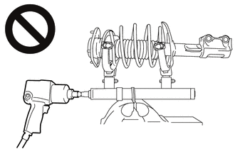
Do not use an impact wrench.
-
The threads may be stripped, or the sudden compression may result in slack that causes the hooks to slip off, causing the spring to fly out and possibly resulting in injury.
-
If a stopper pin touches the coil spring while using SST, remove the stopper pin and continue with the procedure.
-
If a stopper pin is removed, install a coil spring stopper belt as shown in the illustration.
- SST
- 09727-00110
-
-
Check that the rear coil spring has become free, and remove the rear support to rear shock absorber lock nut.
CAUTION:
-
If the rear coil spring has not become free, do not remove the rear support to rear shock absorber lock nut.
-
The spring force will cause the components to be scattered, possibly resulting in injury.
-
-
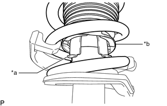
*a Rear Shock Absorber Assembly LH Claw *b End of Rear Upper Coil Spring Insulator Remove the rear suspension support assembly from the rear shock absorber assembly LH.
Note
Turn the rear suspension support assembly to disengage the end of the rear upper coil spring insulator from the rear shock absorber assembly LH claws.
-
Remove the rear upper coil spring insulator from the rear suspension support assembly.
-
Remove the rear No. 1 spring bumper from the rear suspension support assembly.
-
Remove the rear coil spring and SST.
Note
Do not use an impact wrench. It will damage SST.
-
Remove the rear lower coil spring insulator from the rear shock absorber assembly LH.
-