AIR CONDITIONING SYSTEM DETAILS
-
FUNCTION OF MAIN COMPONENTS
-
The ventilation system (without automatic air conditioning system) and manual heater system consist of the following parts:
Component Function Air Conditioning Control Assembly Allows operation and adjustment of the air conditioning system via the switches. Heater Radiator Unit Sub-assembly* A Straight Flow Aluminum-II (SFA-II) heater radiator is used for compactness and high performance. Blower with Fan Motor Sub-assembly High magnetic force magnets and ball bearings are used to achieve a compact and lightweight assembly. Clean Air Filter Removes other particles to provide a comfortable interior space.
-
*: Models with manual heater system
-
-
The manual air conditioning system and automatic air conditioning system consist of the following parts:
Component Function Air Conditioning Control Assembly*1 Allows operation and adjustment of the air conditioning system via the switches. Integration Panel Sub-assembly*2 Air Conditioning Amplifier Assembly Transmits and receives data to and from the switches and sensors. Cooler Compressor Assembly A fixed displacement cooler compressor assembly is used. Cooler Condenser Assembly A Multi-Flow-IV (MF-IV) sub-cool condenser is used to improve heat exchange efficiency. Heater Radiator Unit Sub-assembly A Straight Flow Aluminum-II (SFA-II) heater radiator is used for compactness and high performance. Blower with Fan Motor Sub-assembly High magnetic force magnets and ball bearings are used to achieve a compact and lightweight assembly. No. 1 Cooler Evaporator Sub-assembly A Revolutionary super-slim Structure (RS) is used for compactness. No. 1 Cooler Thermistor Detects the temperature of the No. 1 cooler evaporator sub-assembly and transmits the data to the air conditioning amplifier assembly. Cooler Expansion Valve Sprays the refrigerant in an atomized form. Cooler Thermistor (Ambient Temperature Sensor)*2 Detects ambient temperature and outputs it to the air conditioning amplifier assembly via the combination meter assembly. Cooler Thermistor (Room Temperature Sensor)*2 Detects room temperature and outputs it to the air conditioning amplifier assembly. Cooler Thermistor (Solar Sensor)*2 Detects the changes in the amount of solar energy and outputs them to the air conditioning amplifier assembly. Damper Servo Sub-assembly*2 Receives the input of the operation signals from the fresh-air/recirculation selector switch via the air conditioning amplifier assembly, operates the motor, and opens and closes the fresh-air/recirculation damper. Mode Damper Servo Sub-assembly*2 Receives the input of the operation signals from the mode selector switch via the air conditioning amplifier assembly, operates the motor, and opens and closes the mode damper. Air Mix Control Servo Motor*2 Operates the motor to open and close the air mix damper upon receiving the input of the operation signals from the temperature setting dial via the air conditioning amplifier assembly, or when the system is operating under auto control. Clean Air Filter Removes other particles to provide a comfortable interior space. ECM Receives the signals from the engine coolant temperature sensor and transmits them to the air conditioning amplifier assembly. Air Conditioning Pressure Sensor Mounted on the high-pressure pipe, this sensor etc. controls the compressor assembly. Quick Heater Assembly (PTC Heater)*3 Consists of a Positive Temperature Coefficient (PTC) element, an aluminum fin and a brass plate.
-
*1: Models with manual air conditioning system
-
*2: Models with automatic air conditioning system
-
*3: Models with quick heater assembly (PTC heater)
-
-
-
SYSTEM CONTROL
-
The air conditioning system uses the following controls:
Control Outline Outlet Air Temp. Control MAX Fix Control This control sets the outlet air temperature to -200°C when the temperature is set to MAX COOL, and to 200°C when the temperature is set to MAX HOT. Air Mix Damper Control This function provisionally calculates the required outlet air temperature through an arithmetic circuit in the air mix damper using the output signals from various sensors, and adjusts the value in accordance with signals from the evaporator temperature sensor and water temperature sensor. It then determines the appropriate air mix damper opening angle in accordance with the temperature control switch setting. Blower Control Manual Control Sets the blower speed in accordance with the operation of the blower switch. Automatic Control Time-Lagged Air Flow Control:
2 types of time-lagged air flow control (in accordance with the temperature detected by the evaporator temperature sensor) help prevent hot air from being emitted from the FACE or BI-LEVEL vent.
Sunlight Air Flow Control:
Controls the blower speed in accordance with the intensity of the sunlight when the air outlet is in FACE or BI-LEVEL. The blower speed can be adjusted in response to the signal received from the solar sensor.
Air Outlet Control Manual Control Changes the air outlet in accordance with the selected position of the mode select switch. Automatic Control Mode Damper Switching Servomotor Control:
When the AUTO switch of the heater control panel has been turned on, automatic control causes the mode servomotor to rotate to a desired position in accordance with the target damper opening, which is based on the calculation of the outlet air temperature. (On the models with the automatic cooler, this function switches the damper to FACE or BI-LEVEL.)
Compressor Control When the DEF mode switch is turned on, the magnetic clutch relay is activated automatically to engage the compressor. Also, when the blower is turned off, and the front defroster switch is turned on, the blower will turn on in the automatic control condition. Self-diagnosis Checks the indicator, sensor and actuator in accordance with operation of the heater control panel switches, and then a Diagnostic Trouble Code (DTC) is displayed on the LCD portion to indicate if there is a malfunction or not. -
Quick Heater Control
-
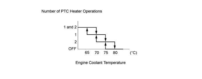
The on/off function of the quick heater assembly is controlled by the air conditioning amplifier assembly in accordance with the engine coolant temperature, engine speed, air mix setting, and electrical load (generator power ratio).
-
For example, the heating value of the operating quick heater assemblies varies depending on the engine coolant temperature, as shown in the graph below:
-
-
Hot-gas Type Power Heater Control
-
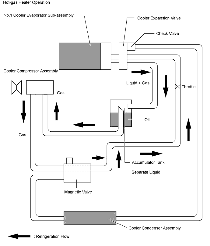
Outline of Refrigeration Cycle with Hot-gas Type Power Heater
-
The hot-gas type power heater system uses the following controls:
Control Outline Hot-gas Type Power Heater Operation Judgment The air conditioning amplifier assembly operates the hot-gas type power heater in accordance with the signals from the power heater switch, A/C switch, blower controller switch, cooler thermistor (ambient temperature sensor) and water temperature sensor. Cooler Thermistor (Ambient Temperature Sensor) Judgment The air conditioning amplifier assembly turns the hot-gas type power heater on/off in accordance with the signals from the cooler thermistor (ambient temperature sensor). Refrigerant Pressure Judgment The air conditioning amplifier assembly turns the hot-gas type power heater on/off in accordance with the refrigerant pressure, in order to protect the cycle.
-
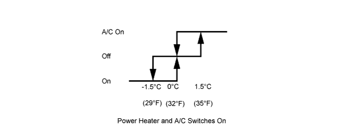
The hot-gas heater turns off when the pressure is above 2.0 MPa, turns back on when the ignition switch is turned off, and resumes operating if the pressure is below 1.5 MPa.
No. 1 Cooler Thermistor Judgment The air conditioning amplifier assembly turns the hot-gas type power heater on/off in accordance with the evaporator temperature, in order to protect the cycle. Windshield Frosting Prevention When the operation is switched from air conditioning to heater, the moisture that has accumulated on the evaporator vaporizes and fogs the windshield. To prevent this from occurring, this function estimates the windshield temperature based on the ambient temperature and the water temperature, and compares it to the target air outlet temperature.
-
The hot-gas type power heater turns off when the windshield temperature is lower than the target air outlet temperature.
Refrigerant Shortage Judgment The hot-gas type power heater turns off when a shortage of refrigerant is determined from the ambient temperature and the refrigerant pressure. -
-
Operating
-
Hot-gas type power heater operates when all of the following conditions have been met:
-
The heater switch assembly and MAX hot switch are on.
-
The ambient temperature is between -30°C (-22°F) and 5°C (41°F).
-
The blower controller switch is turned on.
-
The water temperature is 70°C (158°F) or less.
-
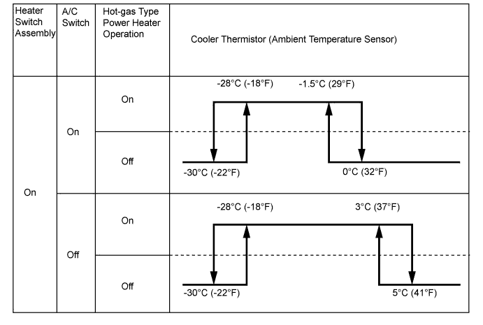
The hot-gas type power heater operation range will be as shown below when the A/C switch is turned on during a hot-gas type power heater operation, because the cycle is being shared:
-
-
Cooler Thermistor (Ambient Temperature Sensor) Judgment
The air conditioning amplifier assembly turns the hot-gas heater on and off in accordance with the cooler thermistor (ambient temperature sensor) signal when it determines that the heater is unnecessary because the ambient temperature is high, or to protect the compressor at extremely low temperatures.
-
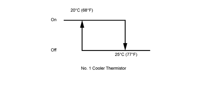
No. 1 Cooler Thermistor Judgment
To protect the cycle, the air conditioning amplifier assembly turns the hot-gas heater on and off in accordance with the No. 1 cooler thermistor signal.
-
-
Viscous Type Power Heater Control
-
The viscous type power heater increases the water temperature by utilizing the sheer heat of the silicon oil and by increasing the engine load.
-
Operating
-
The viscous type power heater, which is located on the top of the engine, is driven by a drive belt. Pressing the heater switch assembly provided in the instrument panel engages the magnetic clutch, causing the rotor in the power heater to rotate and the silicon oil to mix. The sheer heat that is generated heats the water.
-
The viscous type power heater is controlled in accordance with engine speed and water temperature as follows. While the power heater is engaged, the engine idling speed increases to 1200 rpm.
-
The heater will be turned off when the engine speed is 2500 rpm or more, or when the water temperature is 70°C or more.
-
The heater will be turned on when the engine speed is less than 2500 rpm, or when the water temperature is less than 70°C.
Tech Tips
However, the viscous type power heater is turned off when the engine is cranking or the vehicle is accelerating (for 5 seconds while the vehicle speed is under 30 km/h (19 mph) and the throttle opening angle is more than 45%).
-
-
-
-
CONSTRUCTION
-
Air Conditioning Control Assembly
-
Air Conditioning Control Assembly
-
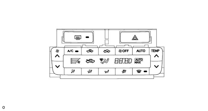
A rotary switch type air conditioning control assembly is used.
-
5 air outlet modes are provided on the control panel on the models with manual air conditioning, and 2 air outlet modes are provided on the models with ventilation system (without air conditioning system).
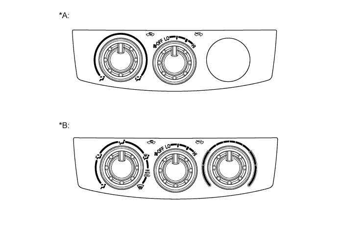
Text in Illustration *A Models with Ventilation System (without Air Conditioning System) *B Models with Manual Heater System and Manual Air Conditioning System
-
A control cable is used. This cable is circular, and is placed around the cable pulleys that are provided at the air conditioning control assembly and the damper.
-
The operation effort of the air conditioning control assembly is transmitted to the damper via the control cable, which always moves in the pulling direction. Due to the consistent action point of the pulleys, the fluctuation of the operating effort has been minimized through the use of the pulleys. These measures have ensured ease of use and have reduced the operating effort.
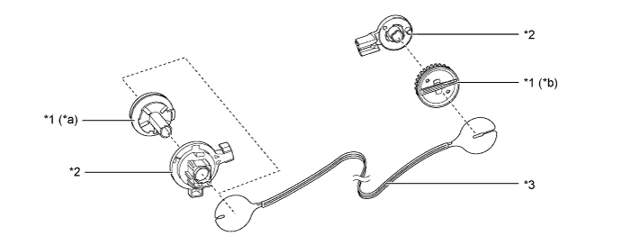
Text in Illustration *1 Pulley *2 Base of Pulley *3 Control Cable - - *a Air Conditioning Control Assembly Side *b Damper Side -
-
Integration Panel Sub-assembly
-
An integration panel sub-assembly with Liquid Crystal Display (LCD) is used to ensure excellent visibility.
-
A push button type integration panel sub-assembly is used.
-
-
-
Air Conditioning Unit
-
A semi-center location air conditioning unit is used, in which the evaporator and heater radiator are placed in the vehicle's longitudinal direction. As a result, the air conditioning unit has been made compact and lightweight.
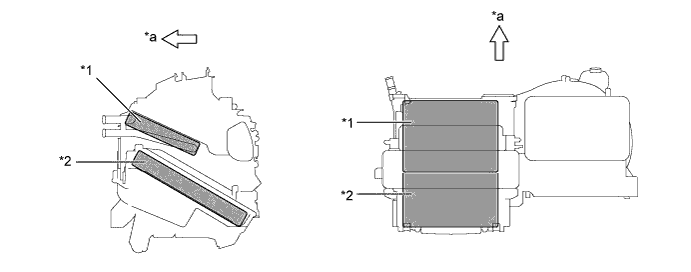
Text in Illustration *1 Heater Radiator Unit Sub-assembly *2 No. 1 Cooler Evaporator Sub-assembly *a Front - - -
A partial recirculation system is used. This system has an air inlet control door (sub) in the air inlet duct. Thus, it is able to cycle a small volume of recirculated air even in the FRESH mode, thus enhancing heating performance. When the blower switch is on, the suction force of the blower fan opens this air inlet control door (sub).
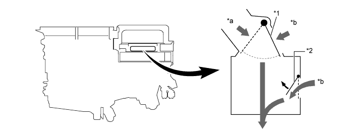
Text in Illustration *1 Air Inlet Control Door *2 Air Inlet Control Door (Sub) *a Fresh Air *b Recirculated Air
-
-
No. 1 Cooler Evaporator Sub-assembly
-
A Revolutionary super-slim Structure (RS) evaporator is used. By placing the tanks at the top and the bottom of the No. 1 cooler evaporator sub-assembly and by using a micropore tube construction, the following effects have been achieved:
-
Heat exchanging efficiency is ensured.
-
Temperature distribution is made uniform.
-
The No. 1 cooler evaporator sub-assembly is made thinner.
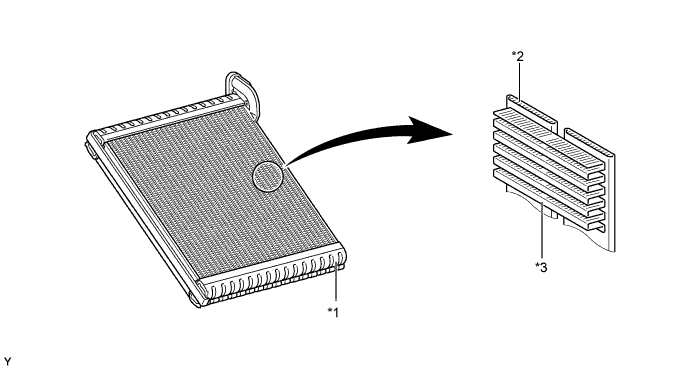
Text in Illustration *1 Tank *2 Micropore Tube *3 Cooling Fin - - -
-
-
No. 1 Cooler Thermistor
-
The No. 1 cooler thermistor detects the temperature of the cool air immediately past the No. 1 cooler evaporator sub-assembly in the form of resistance changes, and outputs it to the air conditioning amplifier assembly.
-
-
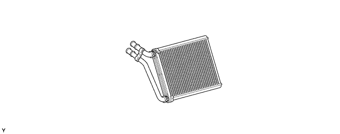
Heater Radiator Unit Sub-assembly
-
This heater radiator unit sub-assembly has been made more compact and performance has been improved by making the core section finer and improving the shapes of the tank section and flow section. Also, the environment has been considered.
-
-
Blower with Fan Motor Sub-assembly
-
The blower assembly has a built-in blower controller, and is controlled using duty control performed by the air conditioning amplifier assembly.
-
-
Quick Heater Assembly (PTC Heater)
-
The quick heater assembly is located above the heater radiator unit sub-assembly in the air conditioning unit.
-
The quick heater assembly consists of a PTC element, an aluminum fin, and a brass plate. When current is applied to the PTC element, it generates heat to warm the air that passes through the unit.
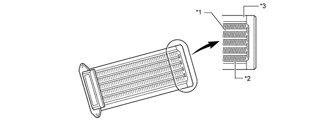
Text in Illustration *1 PTC Element *2 Aluminum Fin *3 Brass Plate - -
-
-
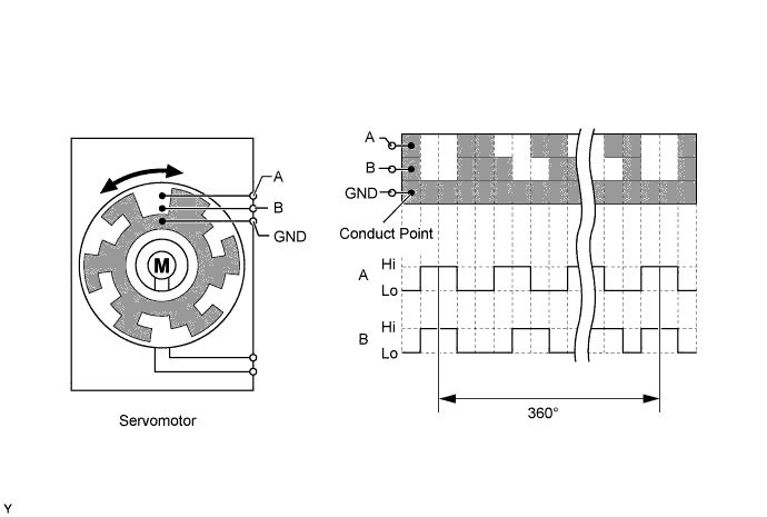
Servomotor
-
The pulse pattern type servomotor consists of a printed-circuit board and a servomotor. The printed-circuit board has three contact points, and transmits the two on and off signals with different pulse phases to the bus connector. The bus connector detects the damper position and movement direction with these signals, and transmits the results to the air conditioning amplifier.
-
After the negative battery terminal cable has been reconnected, the air conditioning amplifier initializes both the mode and air inlet servomotors twice: once when the ignition switch is turned to ON and then turned off. The DEF light inside the heater control panel flashes while initializing.
-
-
Clean Air Filter
-
A high efficiency type clean air filter is used. The clean air filter is installed in the upper section of the blower fan for easy replacement of the clean air filter without the need for removing the one-touch clip in the glove box.
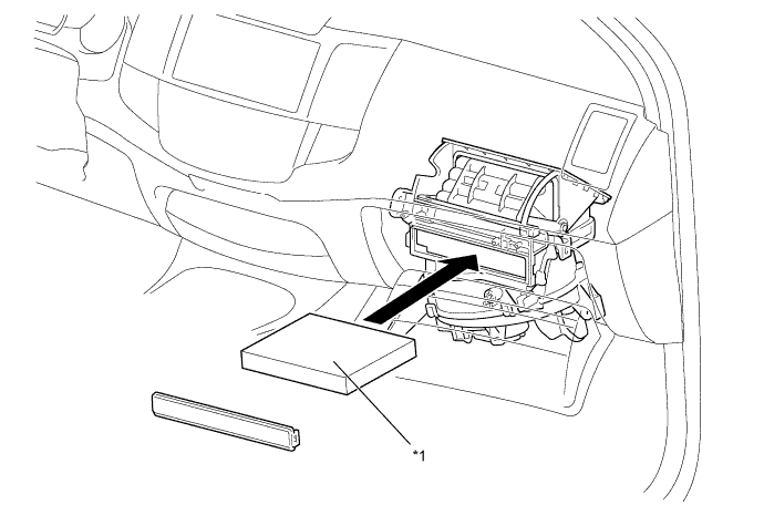
Text in Illustration *1 Clean Air Filter - -
-
-
Cooler Condenser Assembly
-
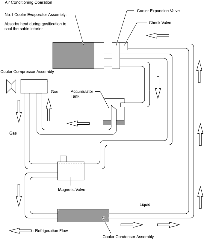
In the sub-cool cycle, after the refrigerant passes through the condensing portion of the condenser assembly, both the liquid refrigerant and the gaseous refrigerant that could not be liquefied are cooled again in the super-cooling portion. Thus, the refrigerant is sent to the No. 1 cooler evaporator sub-assembly in an almost completely liquefied state.
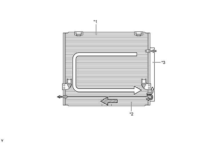
Text in Illustration *1 Condensing Portion *2 Super-cooling Portion *3 Modulator - - 
Gaseous Refrigerant 
Liquid Refrigerant Tech Tips
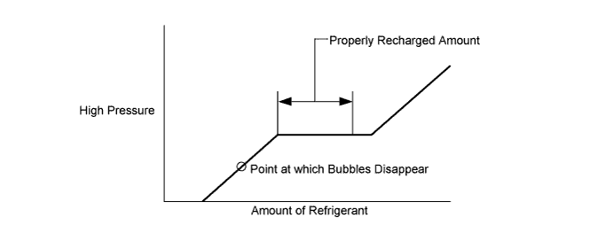
The point at which the air bubbles disappear in the refrigerant of the sub-cool cycle is lower than the proper amount of refrigerant with which the system must be filled. Therefore, if the system is refilled with refrigerant based on the point at which the air bubbles disappear, the amount of refrigerant would be insufficient. As a result, the cooling performance of the system will be affected. If the system is overfilled with refrigerant, this will also lead to reduced performance. For the proper method of verifying the amount of the refrigerant and to refill the system with refrigerant, refer to the corresponding Repair Manual for this model.
-
-
Cooler Compressor Assembly
-
A compact, lightweight, and low-noise 10-cylinder swash plate type cooler compressor is used.
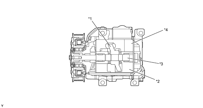
Text in Illustration *1 Swash Plate *2 Piston *3 Shaft *4 Swash Plate Chamber
-
-
Cooler Thermistor (Room Temperature Sensor)
-
The cooler thermistor (room temperature sensor) detects the room temperature based on changes in the resistance of its built-in thermistor, and outputs a signal. This signal is used by the air conditioning amplifier assembly.
-
-
Cooler Thermistor (Ambient Temperature Sensor)
-
The cooler thermistor (ambient temperature sensor) detects the ambient temperature based on changes in the resistance of its built-in thermistor, and outputs a signal. This signal is used by the air conditioning amplifier assembly.
-
-
Cooler Thermistor (Solar Sensor)
-
The cooler thermistor (solar sensor) consists of a photo diode, 2 amplifier circuits for the cooler thermistor (solar sensor), and a frequency converter circuit for the light control sensor.
-
The cooler thermistor (solar sensor) detects (in the form of changes in the current that flows through the built-in photo diode) the changes in the amount of sunlight from its LH and RH sides (2 directions) and outputs these sunlight strength signals to the air conditioning amplifier assembly.
-
-
-
OPERATION
-
Mode Position and Damper Operation
-
Ventilation System (without Air Conditioning System) Model
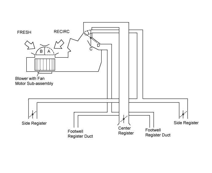
Control Damper Operation Position Damper Position Operation Air Inlet Control Damper FRESH A Brings in fresh air. RECIRC B Recirculates internal air. Mode Control Damper FACE 
C Air blows out of the center registers and side register. BI-LEVEL 
D Air blows out of the center registers, side registers and footwell register ducts. -
Manual Heater System Model
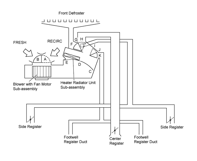
Control Damper Operation Position Damper Position Operation Air Inlet Control Damper FRESH A Brings in fresh air. RECIRC B Recirculates internal air. Air Mix Control Damper MAX COLD to MAX HOT C-D-E Varies the mixture ratio of the cool air and the warm air in order to regulate the temperature continuously from HOT to COLD. Mode Control Damper FACE F, K Air blows out of the center registers and side register. BI-LEVEL F, J Air blows out of the center registers, side registers and footwell register ducts. FOOT 
G, I Air blows out of the footwell register ducts and side register. In addition, air blows out slightly from the front defroster. FOOT/DEF 
H, I Defrosts the windshield through the front defroster and side register, while air is also blown out from the footwell register ducts. DEF 
H, K Defrosts the windshield through the front defroster and side register. -
Manual Air Conditioning System and Automatic Air Conditioning System Model
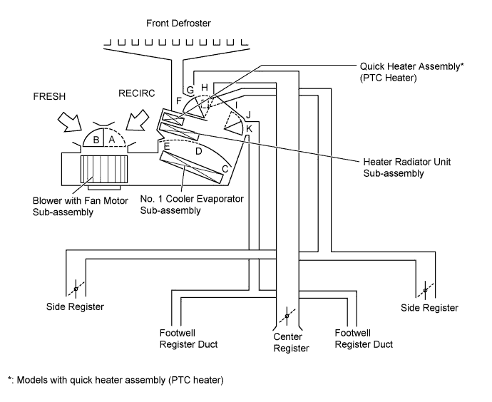
Control Damper Operation Position Damper Position Operation Air Inlet Control Damper FRESH A Brings in fresh air. RECIRC B Recirculates internal air. Air Mix Control Damper MAX COLD to MAX HOT C-D-E Varies the mixture ratio of the cool air and the warm air in order to regulate the temperature continuously from HOT to COLD. Mode Control Damper FACE F, K Air blows out of the center registers and side register. BI-LEVEL F, J Air blows out of the center registers, side registers and footwell register ducts. FOOT G, I Air blows out of the footwell register ducts and side register. In addition, air blows out slightly from the front defroster. FOOT/DEF H, I Defrosts the windshield through the front defroster and side register, while air is also blown out from the footwell register ducts. DEF H, K Defrosts the windshield through the front defroster and side register.
-
-
Air Outlets and Airflow Volume
-
Ventilation System (without Air Conditioning System) Model
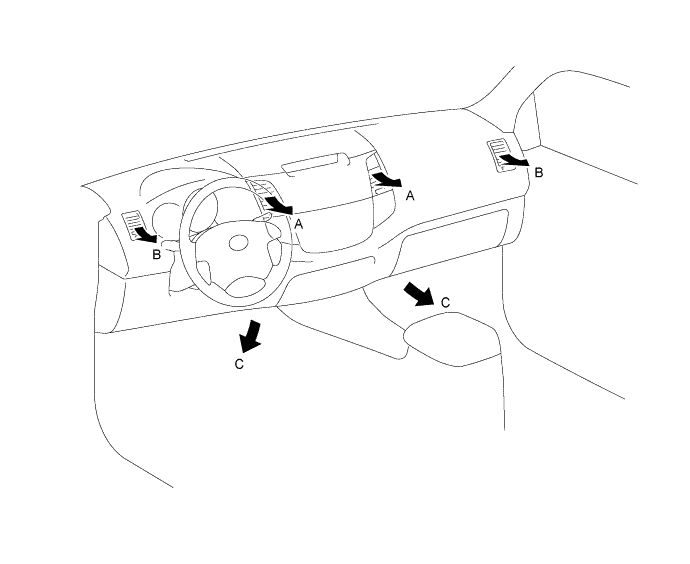
Indication Mode A B C Center Side Footwell FACE 
- BI-LEVEL 

Tech Tips
The size of the circle ○ indicates the proportion of airflow volume.
-
Manual Heater System, Manual Air Conditioning System and Automatic Air Conditioning System Model
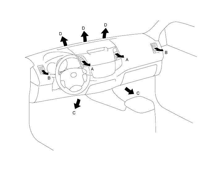
Indication Mode A B C D Center Side Footwell Defroster FACE - - BI-LEVEL - FOOT - 
FOOT/DEF - DEF - - Tech Tips
The size of the circle ○ indicates the proportion of airflow volume.
-
-
-
DIAGNOSIS
-
Diagnostic Trouble Code (DTC)
-
The air conditioning amplifier assembly has a self-diagnosis function. It stores any operation failures in the air conditioning system memory in the form of DTCs. For details, refer to the corresponding Repair Manual for this model.
-
-