СИСТЕМА ECD ДЕТАЛЬНОЕ ОПИСАНИЕ
-
FUNCTION OF MAIN COMPONENTS
-
The main components of the engine control system are as follows:
Component Outline Quantity Function ECM 16-bit CPU 1 The ECM effects overall control of the engine control system to suit the operating conditions of the engine in accordance with the signals provided by the sensors. Intake Air Pressure Sensor Semiconductor Silicon Chip Type 1 This sensor uses built-in semiconductors to detect the intake manifold pressure. Intake Air Temperature Sensor Thermistor Type 1 This sensor detects the intake air temperature by means of an internal thermistor. Crank Position Sensor
(Rotor Teeth/1)
Pick-up Coil Type 1 This sensor detects the engine speed and performs the cylinder identification. Accelerator Pedal Position Sensor Non-contact Type 1 This sensor detects the amount of pedal effort applied to the accelerator pedal. Engine Coolant Temperature Sensor Thermistor Type 1 This sensor detects the engine coolant temperature by means of an internal thermistor. Engine Speed Sensor
(Rotor Teeth/56-8)
Pick-up Coil Type 1 This sensor is attached to the roller ring in the injection pump to detect the engine speed. Spill Control Valve Solenoid Valve Type 1 This valve controls the fuel injection volume in accordance with the signals received from the ECM. Timing Control Valve Duty Solenoid Type 1 This valve controls the fuel injection timing based on signals from the ECM. Fuel Temperature Sensor Thermistor Type 1 This sensor detects the fuel temperature in the injection pump by means of an internal thermistor.
-
-
SYSTEM CONTROL
-
The engine control system has the following features. The ECM controls these systems.
System Outline Fuel Injection Volume Control Based on the signals received from the sensors, the ECM determines the fuel injection volume in accordance with the engine condition. Fuel Injection Timing Control Based on the signals received from the sensors, the ECM determines the fuel injection timing in accordance with the engine condition. Idle Speed Control The ECM determines the idle speed in accordance with the engine condition, and controls the fuel injection volume in order to maintain the target idle speed. Glow Plug Control Controls the length of time when the current is applied to the glow plugs, in accordance with engine coolant temperature. Diesel Throttle Control Fully closes the diesel throttle valve in order to reduce the vibration when the engine is stopped. Air Conditioning Cut-off Control* By controlling the air conditioning compressor on or off in accordance with the engine condition, driveability is maintained. Diagnosis When the ECM detects a malfunction, it diagnoses and memorizes the failed section. Fail-safe When the ECM detects a malfunction, it stops or controls the engine in accordance with the data already stored in the memory.
-
*: Models with air conditioning system
-
-
-
FUNCTION
-
Fuel Injection Volume Control
-
Based on sensor signals, the ECM controls the fuel injection volume by calculating the fuel injection volume that is appropriate for the engine condition.
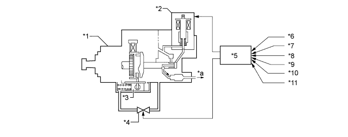
Text in Illustration *1 Injection Pump Assembly *2 Spill Control Valve *3 Timer Piston *4 Timing Control Valve *5 ECM *6 Engine Speed Signal *7 Engine Coolant Temperature Signal *8 Intake Air Temperature Signal *9 Intake Air Pressure Signal *10 Fuel Temperature Signal *11 Vehicle Speed Signal - - *a Fuel (to Injection Nozzle) - - -
The ECM calculates the basic injection volume based on the accelerator pedal opening and engine speed, and the maximum injection volume for the engine condition. The two injection volumes are compared, and the lesser of the two is selected. A correction value, which is obtained via the fuel pump calibration unit, is added to that injection volume, thus determining the fuel injection volume.
Function of ECM Control Function Basic Injection Volume Determined in accordance with the throttle opening and the engine speed. Maximum Injection Volume General Based on the signals received from the sensors, correction values are added to the theoretically required injection volume (basic maximum injection volume) to determine the maximum injection volume during engine operation. Basic Maximum Injection Volume Determined in accordance with the engine speed. Intake Air Pressure Correction Corrects the basic maximum injection volume in accordance with the intake air pressure. Intake Air Temperature Correction Corrects the variance in the air-fuel ratio that is created by the difference in the density of the intake air in accordance with the intake air temperature. The higher the intake air temperature becomes, the smaller the injection volume becomes. Fuel Temperature Correction Corrects the variance in the injection volume that is created by the difference in the density of the fuel in accordance with the fuel temperature. The higher the fuel temperature becomes, the larger the injection volume becomes. Starting Injection Volume Control Determines the fuel injection volume during starting in accordance with the starting signal and the engine coolant temperature signal. When the engine is cold, the lower the engine coolant temperature becomes, the larger the injection volume becomes.
-
-
Fuel Injection Timing Control
-
Based on signals received from the sensors, the ECM calculates and controls the fuel injection timing that is optimal for the engine condition.
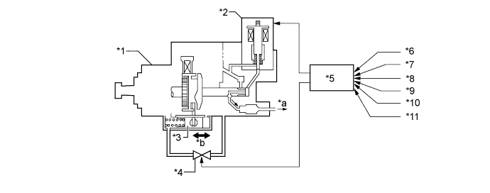
Text in Illustration *1 Injection Pump Assembly *2 Spill Control Valve *3 Timer Piston *4 Timing Control Valve *5 ECM *6 Engine Speed Signal *7 Engine Coolant Temperature Signal *8 Vehicle Speed Signal *9 Intake Air Pressure Signal *10 Crank Position Signal *11 Start Signal - - *a Fuel (to Injection Nozzle) *b Movement of Timer Piston -
The ECM adds the corrections from the sensor signals to the basic fuel injection timing to calculate the fuel injection timing that is optimal for the engine condition.
Function of ECM Control Function Basic Injection Timing The basic injection timing is determined in accordance with the injection volume and the engine speed. Injection Timing Correction Intake Air Pressure Correction Corrects the basic fuel injection timing in accordance with the intake air pressure. The injection timing is advanced when the intake air pressure is low such as in high altitude areas. Engine Coolant Temperature Correction Corrects the basic fuel injection timing in accordance with the engine coolant temperature. The injection timing is advanced when the engine coolant temperature is low. Starting Injection Timing Control The starting injection timing is determined in accordance with the starting signal, engine coolant temperature signal, and engine speed. The injection timing is advanced when the engine coolant temperature is low and engine speed is high.
-
-
Idle Speed Control
-
In this system, the ECM calculates the target engine speed in accordance with the engine condition, and determines the fuel injection volume, thus controlling the idle speed.

Text in Illustration *A Models with Air Conditioning System - - *1 Injection Pump Assembly *2 Spill Control Valve *3 ECM *4 Engine Speed Signal *5 Engine Coolant Temperature Signal *6 Vehicle Speed Signal *7 Air Conditioning Switch Signal *8 Start Signal *a Fuel (to Injection Nozzle) - - Function of ECM Control Function Feedback Control During idling, the feedback control controls the injection volume to achieve the target idle speed, if there is a difference between the target idle speed calculated by the ECM and the actual idle speed. Warm-up Control Controls the injection volume during warm-up, in accordance with engine coolant temperature, to achieve an optimal fast idle speed. Engine Speed Changes Estimate Control Immediately after the air conditioning switch is engaged, the idle speed can be affected by the change in the load that is applied to the engine. To prevent this symptom, the engine speed changes estimate control increases or decreases the injection volume before the idle speed changes.
-
-
Diesel Throttle Control
-
The opening of the diesel throttle valve is controlled by the ECM in accordance with the engine conditions. This reduces the noise that is generated during idling and deceleration, as well as the noise and vibration that is generated when the engine is stopped.
Text in Illustration *1 Diesel Throttle Valve Fully Opened Switch *2 Throttle Control Motor *3 Diesel Throttle Valve *4 ECM *5 Engine Speed Signal *6 Engine Coolant Temperature Signal *7 Intake Air Pressure Signal *8 Intake Air Temperature Signal *9 Ignition Switch Signal - -
-
-
-
CONSTRUCTION
-
Intake Air Pressure Sensor
-
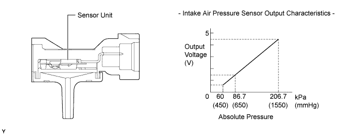
The intake air pressure sensor is mounted on the intake manifold flange.
-
It consists of a semiconductor which utilizes the characteristic of a silicon chip that changes its electrical resistance when pressure is applied to it. The sensor converts the pressure into an electrical signal, and sends it to the ECM in an amplified form.
-
-
Crank Position Sensor
-
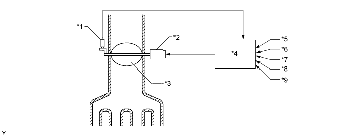
The crank position sensor is installed on the cylinder block. Using the protrusion that is provided on the crankshaft, the sensor generates one signal for every revolution. This signal is then sent to the ECM as a crank position signal.
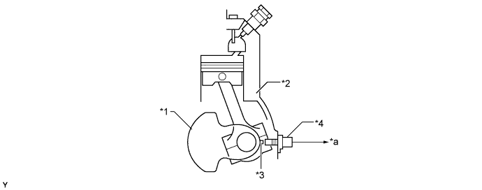
Text in Illustration *1 Crankshaft *2 Cylinder Block *3 Protrusion *4 Crank Position Sensor *a To ECM - -
-
-
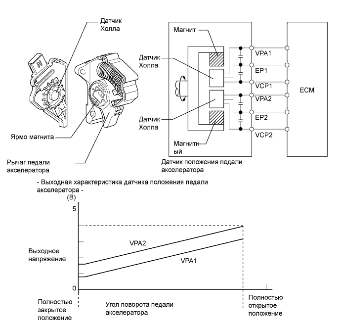
Accelerator Pedal Position Sensor
-
The non-contact type accelerator pedal position sensor uses a Hall IC.
-
The magnetic yoke that is mounted at the base of the accelerator pedal arm moves around the Hall IC in accordance with the amount of effort that is applied to the accelerator pedal. The Hall IC converts the changes in the magnetic flux that occur at that time into electrical signals, and outputs them in the form of accelerator pedal effort to the ECM.
-
This accelerator pedal position sensor includes 2 Hall ICs and circuits for the main and sub signals. It converts the accelerator pedal depressing angles into electric signals with 2 differing characteristics and outputs them to the ECM.
-
-
Engine Speed Sensor
-
The engine speed sensor is attached to the roller ring in the injection pump assembly to detect the engine speed. The timing rotor attached to the drive shaft is missing 2 teeth at each of the 4 locations, and generates a signal every 11.25° (crankshaft angle) with its 56 teeth.
Text in Illustration *1 Injection Pump Assembly *2 Engine Speed Sensor *3 Roller Ring *4 Timing Rotor *5 Timer Piston - -
-
-
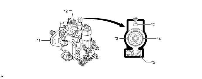
Spill Control Valve
-
The spill control valve controls the fuel injection volume in accordance with the signals received from the ECM. When the current applied to the spill control valve is shut off, the valve in the spill control valve opens by the difference in pressures. Thus, the pressure in the plunger decreases causing the injection nozzle to stop injection fuel. The length of time until the spill control valve is turned off is the same as the fuel injection time. Thus, the fuel injection volume is controlled by increasing or decreasing the length of time until the spill control valve is turned off.
Text in Illustration *1 Injection Pump Assembly *2 Spill Control Valve *3 Pressure Chamber *4 Plunger
-
-
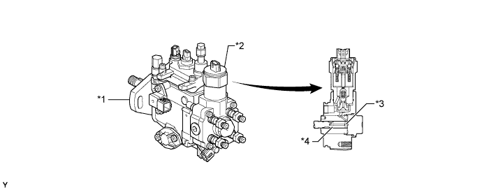
Timing Control Valve
-
In accordance with the signals from the ECM, the timing control valve opens the valve in the fuel passage between the high-pressure chamber and the low-pressure chamber, thus controlling the injection timing. When the current flows to the coil of the timing control valve, the stator core becomes an electromagnet to push and compress the spring. This causes the moving core to retract and open the fuel passage.
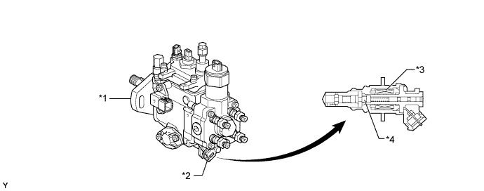
Text in Illustration *1 Injection Pump Assembly *2 Timing Control Valve *3 Coil *4 Moving Core
-
-