FRONT SHOCK ABSORBER(for 2WD) INSTALLATION

CAUTION / NOTICE / HINT
Tech Tips
-
Use the same procedure for the RH and LH sides.
-
The procedure listed below is for the LH side.
PROCEDURE
-
INSTALL FRONT COIL SPRING LH
-
For SST with stopper pins:
-
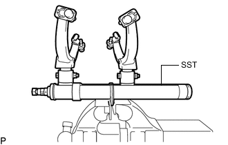
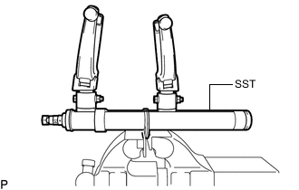
Secure SST in a vise.
- SST
- 09727-30022 ( 09727-00010, 09727-00022, 09727-00031 )
-
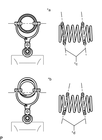
*a Correct *b Incorrect *c Parallel *d Not Parallel Attach the hooks of each SST arm across the diameter of the coil spring.
CAUTION:
-
Make sure that the hooks of the upper and lower arms are attached to the coil spring so that the distance between the hooks is as large as possible.
-
Make sure that the arms of SST are parallel and attached to the coil spring, and the number of coil springs between the hooks on each side is the same.
-
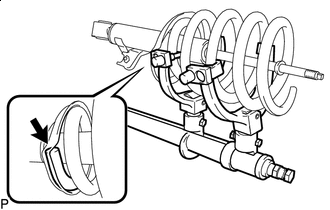
Check that the claws of the hooks are securely attached to the coil spring.
-
-
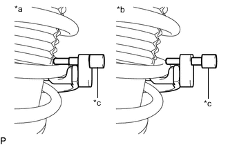
*a Correct *b Incorrect *c Stopper Pin Install the stopper pins to the hooks of SST.
CAUTION:
Make sure that the stopper pins are installed securely.
-
Using SST, compress the coil spring.
CAUTION:
-
If the coil spring bends while using SST, stop immediately and reattach SST correctly.
-
Do not compress the coil spring to the point where the coils touch each other.
-
Do not use an impact wrench.
-
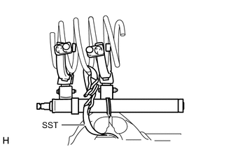
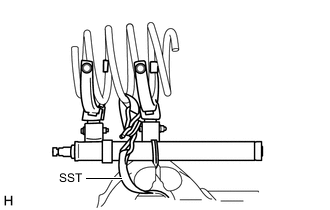
If a stopper pin touches the coil spring while using SST, remove the stopper pin and continue with the procedure. In this case, installing the coil spring stopper belt as shown in the illustration is recommended.
- SST
- 09727-00110
-
-
-
For SST without stopper pins:
-
Secure SST in a vise.
- SST
- 09727-30021 ( 09727-00010, 09727-00021, 09727-00031 )
-
*a Correct *b Incorrect *c Parallel *d Not Parallel Attach the hooks of each SST arm across the diameter of the coil spring.
CAUTION:
-
Make sure that the hooks of the upper and lower arms are attached to the coil spring so that the distance between the hooks is as large as possible.
-
Make sure that the arms of SST are parallel and attached to the coil spring, and the number of coil springs between the hooks on each side is the same.
-
Check that the claws of the hooks are securely attached to the coil spring.
-
-
Using SST, compress the coil spring.
CAUTION:
-
If the coil spring bends while using SST, stop immediately and reattach SST correctly.
-
Do not compress the coil spring to the point where the coils touch each other.
-
Do not use an impact wrench.
Tech Tips
Installing SST as shown in the illustration is recommended.
- SST
- 09727-00110
-
-
-

Recess Install the coil spring to the front shock absorber assembly LH. Fit the lower end of the coil spring into the recess of the spring lower seat.
-
-
INSTALL FRONT UPPER COIL SPRING INSULATOR LH
-
Install the front coil spring upper insulator LH to the front shock absorber assembly LH.
-
-
INSTALL FRONT SUSPENSION SUPPORT SUB-ASSEMBLY LH
-
Install the front shock absorber cushion retainer to the front shock absorber assembly LH.
-
Install the front suspension support sub-assembly LH to the front shock absorber assembly LH.
-
-
INSTALL FRONT NO. 1 SHOCK ABSORBER CUSHION
-
Install the front No. 1 shock absorber cushion to the front shock absorber assembly LH.
-
-
INSTALL FRONT SHOCK ABSORBER CUSHION RETAINER
-
Install the front shock absorber cushion retainer to the front shock absorber assembly LH.
-
-
INSTALL FRONT SUPPORT TO FRONT SHOCK ABSORBER NUT
-
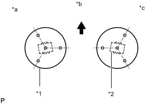
*1 Front Suspension Support Sub-assembly *2 Absorber Bush *a for LH *b Front of the Vehicle *c for RH Align the front suspension support sub-assembly and absorber bushes as shown in the illustration.
-
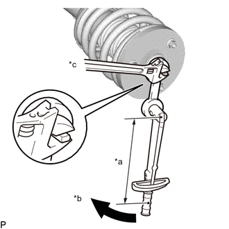
*a Torque Wrench Fulcrum Length *b Turn *c Hold Using a ball joint lock nut wrench, install a new lock nut.
- Torque:
- Specified tightening torque
- 18 N*m { 184 kgf*cm, 13 ft.*lbf }
Note
Do not use an impact wrench. It will damage the shock absorber rod.
Tech Tips
-
Calculate the torque wrench reading when changing the fulcrum length of the torque wrench.
-
When using a ball joint lock nut wrench (fulcrum length of 149 mm (5.8661 in.)) + torque wrench (fulcrum length of 300 mm (11.8110 in.)): 12 N*m (122 kgf*cm, 9 ft.*lbf)
-
Release the coil spring while checking the position of the spring lower seat and suspension support.
-
-
TEMPORARILY INSTALL FRONT SHOCK ABSORBER WITH COIL SPRING
-
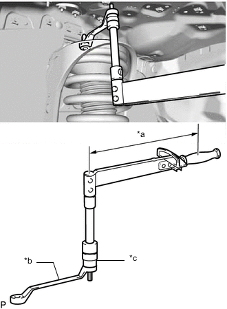
*a Torque Wrench Fulcrum Length *b 12 x 14 mm Long Offset Wrench *c 12 mm Socket Hexagon Wrench Using a 12 mm socket hexagon wrench and 12 x 14 mm long offset wrench, install the 3 nuts to the upper side of the shock absorber with coil spring.
- Torque:
- Specified tightening torque
- 40 N*m { 408 kgf*cm, 30 ft.*lbf }
Tech Tips
-
Calculate the torque wrench reading when changing the fulcrum length of the torque wrench.
-
When using a long offset wrench (fulcrum length of 206.25 mm (8.1201 in.)) + torque wrench (fulcrum length of 380 mm (14.9606 in.)): 25.9 N*m (264 kgf*cm, 19 ft.*lbf)
-
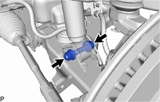
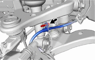
Temporarily install the bolt and nut as shown in the illustration.
Tech Tips
Fix the nut in place and temporarily install the bolt.
-
-
INSTALL FRONT UPPER SUSPENSION ARM
-
CONNECT FRONT SPEED SENSOR LH (w/ ABS)
-
Connect the front speed sensor LH with the bolt.
- Torque:
- 32 N*m { 326 kgf*cm, 24 ft.*lbf }
-
-
CONNECT FRONT FLEXIBLE HOSE
-
Connect the front flexible hose with the bolt.
- Torque:
- 29 N*m { 296 kgf*cm, 21 ft.*lbf }
-
-
INSTALL FRONT WHEEL
-
STABILIZE SUSPENSION
-
Lower the vehicle.
-
Press down on the vehicle several times to stabilize the suspension.
-
-
TIGHTEN FRONT SHOCK ABSORBER WITH COIL SPRING
-
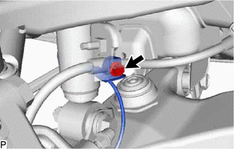
Fix the nut in place and tighten the bolt.
- Torque:
- 110 N*m { 1122 kgf*cm, 81 ft.*lbf }
Note
Do not tighten the nut.
-
-
INSPECT AND ADJUST FRONT WHEEL ALIGNMENT