IMMOBILISER SYSTEM(w/ Entry and Start System), Diagnostic DTC:B2799
| DTC Code | DTC Name |
|---|---|
| B2799 | Immobiliser Malfunction |
DESCRIPTION
w/ Multi-information Display (Dot Display Type):
When there is a communication malfunction between the ECM and ID code box (immobiliser code ECU), or when the communication ID codes do not match, the ECM stores this DTC.
w/ Multi-information Display (Segment Display Type):
When there are communication malfunctions between the ECM and certification ECU (smart key ECU assembly), or when the communication ID codes do not match, the ECM stores this DTC.
DTC No. |
Detection Item |
DTC Detection Condition |
Trouble Area |
Note |
|---|---|---|---|---|
B2799 |
Immobiliser Malfunction |
Either condition is met (1 trip detection logic*3):
|
|
DTC output confirmation operation (Either condition is met):
|
*1: w/ Multi-information Display (Dot Display Type)
*2: w/ Multi-information Display (Segment Display Type)
*3: Only output while a malfunction is present.
*4: except Manual Transaxle
*5: for Manual Transaxle
*6: w/ Blocking System
Vehicle Condition when Malfunction Detected |
Fail-safe Operation when Malfunction Detected |
|---|---|
Engine cannot be started |
- |
DTC No. |
Data List and Active Test |
|---|---|
B2799 |
- |
WIRING DIAGRAM
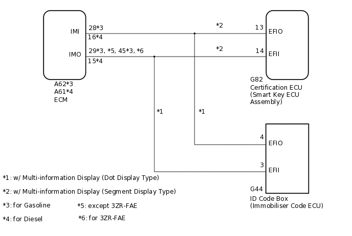
1. w/o Blocking System
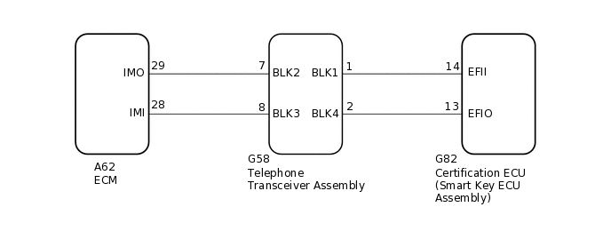
2. w/ Blocking System
CAUTION / NOTICE / HINT
When replacing the certification ECU (smart key ECU assembly)*1, ID code box (immobiliser code ECU)*2 or telephone transceiver assembly*3, refer to the Service Bulletin.
After repair, confirm that no DTCs are output by performing "DTC Output Confirmation Operation".
When the telephone transceiver assembly is replaced, it is necessary to set the contract mode.*3
*1: w/ Multi-information Display (Segment Display Type)
*2: w/ Multi-information Display (Dot Display Type)
*3: w/ Blocking System
When DTC B2799 and a certification ECU (smart key ECU assembly) DTC are output simultaneously, first perform troubleshooting for the certification ECU (smart key ECU assembly) DTC.
PROCEDURE
SYSTEM CHECK
Check the vehicle specification.
Result
Proceed to
w/o Blocking System
w/ Blocking System
w/ Blocking System CHECK HARNESS AND CONNECTOR (ECM - TELEPHONE TRANSCEIVER ASSEMBLY)Click here
CHECK HARNESS AND CONNECTOR (ID CODE BOX [IMMOBILISER CODE ECU] OR CERTIFICATION ECU [SMART KEY ECU ASSEMBLY] - ECM)
*1: w/ Multi-information Display (Dot Display Type)
*2: w/ Multi-information Display (Segment Display Type)
*3: for Gasoline
*4: for Diesel
Disconnect the G44 ID code box (immobiliser code ECU) connector.*1
Disconnect the G82 certification ECU (smart key ECU assembly) connector.*2
Disconnect the A62*3 or A61*4 ECM connector.
Measure the resistance according to the value(s) in the table below.
Standard Resistance
Table 3. for Gasoline Tester Connection
Condition
Specified Condition
G44-3 (EFII) - A62-29 (IMO)*1
Always
Below 1 Ω
G82-14 (EFII) - A62-29 (IMO)*2
A62-29 (IMO) - Body ground
Always
10 kΩ or higher
G44-3 (EFII) - Body ground*1
Always
10 kΩ or higher
G82-14 (EFII) - Body ground*2
Always
10 kΩ or higher
G44-4 (EFIO) - A62-28 (IMI)*1
Always
Below 1 Ω
G82-13 (EFIO) - A62-28 (IMI)*2
A62-28 (IMI) - Body ground
Always
10 kΩ or higher
G44-4 (EFIO) - Body ground*1
Always
10 kΩ or higher
G82-13 (EFIO) - Body ground*2
Always
10 kΩ or higher
Table 4. for Diesel Tester Connection
Condition
Specified Condition
G44-3 (EFII) - A61-15 (IMO)*1
Always
Below 1 Ω
G82-14 (EFII) - A61-15 (IMO)*2
A61-15 (IMO) - Body ground
Always
10 kΩ or higher
G44-3 (EFII) - Body ground*1
Always
10 kΩ or higher
G82-14 (EFII) - Body ground*2
Always
10 kΩ or higher
G44-4 (EFIO) - A61-16 (IMI)*1
Always
Below 1 Ω
G82-13 (EFIO) - A61-16 (IMI)*2
A61-16 (IMI) - Body ground
Always
10 kΩ or higher
G44-4 (EFIO) - Body ground*1
Always
10 kΩ or higher
G82-13 (EFIO) - Body ground*2
Always
10 kΩ or higher
*1: w/ Multi-information Display (Dot Display Type)
*2: w/ Multi-information Display (Segment Display Type)
Result
Proceed to
OK
NG
NG REPAIR OR REPLACE HARNESS OR CONNECTOR
REGISTER ECU COMMUNICATION ID
Reregister the ECU communication ID.
Tip:Refer to the Service Bulletin.
Result
Proceed to
NEXT
CLEAR DTC
Clear the DTCs.
Powertrain > Engine > Clear DTCs
Powertrain > Engine and ECT > Clear DTCs
Result
Proceed to
NEXT
CHECK FOR DTC
Check for DTCs.
Powertrain > Engine > Trouble Codes
Powertrain > Engine and ECT > Trouble Codes
Tip:Before checking for DTCs, perform the "DTC Output Confirmation Operation" procedure.
Result
Proceed to
B2799 is not output
B2799 is output
Other DTCs are output
B2799 is not output END (COMMUNICATION ID REGISTRATION WAS DEFECTIVE)
REPLACE ECM
Temporarily replace the ECM with a new one.
for 2AR-FE:
for 3ZR-FAE:
for 3ZR-FE:
for 1AD-FTV:
for 2AD-FTV:
for 2AD-FHV:
Result
Proceed to
NEXT
REGISTER ECU COMMUNICATION ID
Reregister the ECU communication ID.
Tip:Refer to the Service Bulletin.
Result
Proceed to
NEXT
CLEAR DTC
Clear the DTCs.
Powertrain > Engine > Clear DTCs
Powertrain > Engine and ECT > Clear DTCs
Result
Proceed to
NEXT
CHECK FOR DTC
Check for DTCs.
Powertrain > Engine > Trouble Codes
Powertrain > Engine and ECT > Trouble Codes
Tip:Before checking for DTCs, perform the "DTC Output Confirmation Operation" procedure.
OK
DTC B2799 is not output.
Result
Proceed to
OK
NG (w/ Multi-information Display [Dot Display Type])
NG (w/ Multi-information Display [Segment Display Type])
OK END (ECM WAS DEFECTIVE)
NG (w/ Multi-information Display [Dot Display Type]) REPLACE ID CODE BOX (IMMOBILISER CODE ECU)
NG (w/ Multi-information Display [Segment Display Type]) REPLACE CERTIFICATION ECU (SMART KEY ECU ASSEMBLY)
CHECK HARNESS AND CONNECTOR (ECM - TELEPHONE TRANSCEIVER ASSEMBLY)
Disconnect the A62 ECM connector.
Disconnect the G58 telephone transceiver assembly connector.
Measure the resistance according to the value(s) in the table below.
Standard Resistance
Tester Connection
Condition
Specified Condition
A62-29 (IMO) - G58-7 (BLK2)
Always
Below 1 Ω
A62-29 (IMO) - Body ground
Always
10 kΩ or higher
G58-7 (BLK2) - Body ground
Always
10 kΩ or higher
A62-28 (IMI) - G58-8 (BLK3)
Always
Below 1 Ω
A62-28 (IMI) - Body ground
Always
10 kΩ or higher
G58-8 (BLK3) - Body ground
Always
10 kΩ or higher
Result
Proceed to
OK
NG
NG REPAIR OR REPLACE HARNESS OR CONNECTOR
CHECK HARNESS AND CONNECTOR (CERTIFICATION ECU [SMART KEY ECU ASSEMBLY] - TELEPHONE TRANSCEIVER ASSEMBLY)
Disconnect the G82 certification ECU (smart key ECU assembly) connector.
Disconnect the G58 telephone transceiver assembly connector.
Measure the resistance according to the value(s) in the table below.
Standard Resistance
Tester Connection
Condition
Specified Condition
G82-14 (EFII) - G58-1 (BLK1)
Always
Below 1 Ω
G82-14 (EFII) - Body ground
Always
10 kΩ or higher
G58-1 (BLK1) - Body ground
Always
10 kΩ or higher
G82-13 (EFIO) - G58-2 (BLK4)
Always
Below 1 Ω
G82-13 (EFIO) - Body ground
Always
10 kΩ or higher
G58-2 (BLK4) - Body ground
Always
10 kΩ or higher
Result
Proceed to
OK
NG
NG REPAIR OR REPLACE HARNESS OR CONNECTOR
REGISTER ECU COMMUNICATION ID
Reregister the ECU communication ID.
Tip:Refer to the Service Bulletin.
Result
Proceed to
NEXT
CLEAR DTC
Clear the DTCs.
Powertrain > Engine and ECT > Clear DTCs
Result
Proceed to
NEXT
CHECK FOR DTC
Check for DTCs.
Powertrain > Engine and ECT > Trouble Codes
Tip:Before checking for DTCs, perform the "DTC Output Confirmation Operation" procedure.
Result
Proceed to
B2799 is not output
B2799 is output
Other DTCs are output
B2799 is not output END (COMMUNICATION ID REGISTRATION WAS DEFECTIVE)
REPLACE TELEPHONE TRANSCEIVER ASSEMBLY
Temporarily replace the telephone transceiver assembly with a new or known good one.
Tip:Refer to the Service Bulletin.
Result
Proceed to
NEXT
REGISTER ECU COMMUNICATION ID
Reregister the ECU communication ID.
Tip:Refer to the Service Bulletin.
Result
Proceed to
NEXT
CLEAR DTC
Clear the DTCs.
Powertrain > Engine and ECT > Clear DTCs
Result
Proceed to
NEXT
CHECK FOR DTC
Check for DTCs.
Powertrain > Engine and ECT > Trouble Codes
Tip:Before checking for DTCs, perform the "DTC Output Confirmation Operation" procedure.
Result
Proceed to
B2799 is not output
B2799 is output
B2799 is not output END (TELEPHONE TRANSCEIVER ASSEMBLY WAS DEFECTIVE)
B2799 is output REPLACE ECMClick here