MULTI-MODE MANUAL TRANSAXLE SYSTEM Parking Brake Switch Circuit
| DTC Code | DTC Name |
|---|---|
| Parking Brake Switch Circuit |
DESCRIPTION
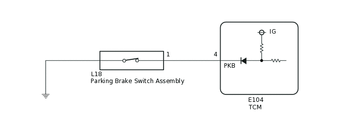
The TCM detects the ON/OFF status of the parking brake switch. When the parking brake is applied, the parking brake switch turns ON. When the parking brake is released, the switch turns OFF.
When the brake pedal is not depressed with the gear in 1st, 2nd or reverse, the clutch is half-engaged, even if the accelerator pedal is not depressed. As a result, the vehicle can creep slowly like an automatic transaxle vehicle. This assists the vehicle in preparing to move. The take off assist control is canceled while the parking brake switch is ON.
WIRING DIAGRAM
PROCEDURE
INSPECT PARKING BRAKE SWITCH ASSEMBLY
-
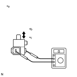
*a
Component without harness connected
(Parking Brake Switch Assembly)
*b
ON
*c
OFF
Remove the parking brake switch assembly.
Measure the resistance according to the value(s) in the table below.
Standard Resistance
Tester Connection
Condition
Specified Condition
1 - Switch body
OFF
(When shaft pressed)
10 kΩ or higher
ON
(When shaft released)
Below 1 Ω
Result
Proceed to
OK
NG
-
CHECK HARNESS AND CONNECTOR (TCM - BODY GROUND)
Connect the parking brake switch assembly connector.
-
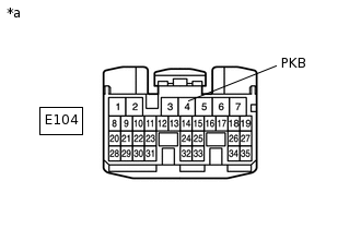
*a
Front view of wire harness connector
(to TCM)
Disconnect the TCM connector.
Measure the resistance according to the value(s) in the table below.
Standard Resistance
Tester Connection
Condition
Specified Condition
E104-4 (PKB) - Body ground
OFF (Parking brake is released)
10 kΩ or higher
ON (Parking brake is applied)
Below 1 Ω
Result
Proceed to
OK
NG
NG REPAIR OR REPLACE HARNESS OR CONNECTOR
INSPECT TCM
Reconnect the TCM connector.
-
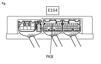
*a
Component with harness connected
(TCM)
Turn the ignition switch to ON.
Measure the voltage according to the value(s) in the table below.
Standard Voltage
Tester Connection
Condition
Specified Condition
E104-4 (PKB) - Body ground
OFF (Parking brake is released)
11 to 14 V
ON (Parking brake is applied)
Below 1 V
Result
Proceed to
OK
NG
REPLACE TCM
Replace the TCM.
Result
Proceed to
NEXT
PERFORM INITIALIZATION
Perform the initialization and learning procedure.
Result
Proceed to
NEXT
NEXT END