SFI SYSTEM(w/o Canister Pump Module), Diagnostic DTC:P012011
| DTC Code | DTC Name |
|---|---|
| P012011 | Throttle / Pedal Position Sensor / Switch "A" Circuit Short to Ground |
DESCRIPTION
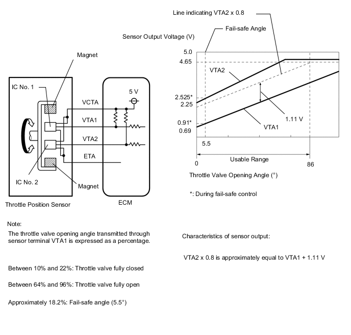
The throttle position sensor is built into the throttle body assembly and detects the opening angle of the throttle valve. This sensor is a non-contact type sensor. It uses Hall-effect elements in order to yield accurate signals even in extreme driving conditions, such as at high speeds as well as very low speeds.
The throttle position sensor has 2 sensor circuits, VTA1 and VTA2, each of which transmits a signal. VTA1 is used to detect the throttle valve angle and VTA2 is used to detect malfunctions in VTA1. The sensor signal voltages vary between 0 V and 5 V in proportion to the throttle valve opening angle, and are transmitted to the VTA1 and VTA2 terminals of the ECM.
As the valve closes, the sensor output voltage decreases and as the valve opens, the sensor output voltage increases. The ECM calculates the throttle valve opening angle according to these signals and controls the throttle actuator in response to a request from the hybrid system. These signals are also used in calculations such as air fuel ratio correction, power increase correction and fuel-cut control.
Tech Tips
-
When throttle position sensor DTCs are output, check the throttle valve opening angle using the GTS. Enter the following menus: Powertrain / Engine / Data List / Throttle Position Sensor No.1 Voltage and Throttle Position Sensor No.2 Voltage.
-
Throttle Position Sensor No.1 Voltage is the VTA1 signal, and Throttle Position Sensor No.2 Voltage is the VTA2 signal.
Reference (Normal Condition) GTS Display Accelerator Pedal Fully Released Throttle Position Sensor No.1 Voltage 0.6 to 1.1 V Throttle Position Sensor No.2 Voltage 2.1 to 3.1 V
| DTC No. | Detection Item | DTC Detection Condition | Trouble Area | MIL | Memory | Note |
|---|---|---|---|---|---|---|
| P012011 | Throttle / Pedal Position Sensor / Switch "A" Circuit Short to Ground | The output voltage of VTA1 is less than 0.56 V for 2 seconds or more (1 trip detection logic). |
|
Comes on | DTC stored | SAE Code: P0122 |
MONITOR DESCRIPTION
The ECM uses the throttle position sensor to monitor the throttle valve opening angle. If the VTA1 terminal voltage is less than the threshold, the ECM will illuminate the MIL and store this DTC.
MONITOR STRATEGY
| Frequency of Operation | Continuous |
CONFIRMATION DRIVING PATTERN
-
Connect the GTS to the DLC3.
-
Turn the power switch on (IG).
-
Turn the GTS on.
-
Clear the DTCs (even if no DTCs are stored, perform the clear DTC procedure).
-
Turn the power switch off and wait for at least 30 seconds.
-
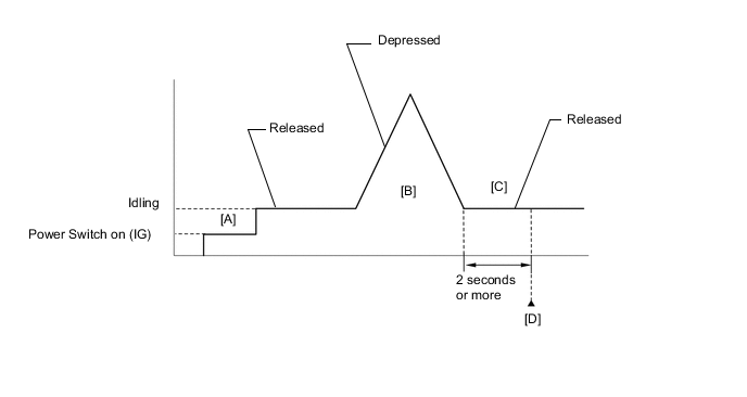
Turn the power switch on (IG) [A].
-
Turn the GTS on.
-
Put the engine in Inspection Mode (Maintenance Mode).
-
Start the engine.
-
With the vehicle stationary, fully depress and release the accelerator pedal [B].
Tech Tips
During charge control, the engine speed is set at idle. Therefore, the engine speed will not increase when the accelerator pedal is depressed. In this case, perform step [B] after charge control has completed.
-
Idle the engine for 2 seconds or more [C].
-
Enter the following menus: Powertrain / Engine / Trouble Codes [D].
-
Read the pending DTCs.
Tech Tips
-
If a pending DTC is output, the system is malfunctioning.
-
If a pending DTC is not output, perform the following procedure.
-
-
Enter the following menus: Powertrain / Engine / Utility / All Readiness.
-
Input the DTC: P012011.
-
Check the DTC judgment result.
GTS Display Description NORMAL
-
DTC judgment completed
-
System normal
ABNORMAL
-
DTC judgment completed
-
System abnormal
INCOMPLETE
-
DTC judgment not completed
-
Perform driving pattern after confirming DTC enabling conditions
N/A
-
Unable to perform DTC judgment
-
Number of DTCs which do not fulfill DTC preconditions has reached ECU memory limit
Tech Tips
-
If the judgment result is NORMAL, the system is normal.
-
If the judgment result is ABNORMAL, the system is malfunctioning.
-
If the judgment result is INCOMPLETE or N/A, perform steps [B] through [D] again.
-
FAIL-SAFE
When this DTC is stored, the ECM enters fail-safe mode. During fail-safe mode, the ECM cuts the current to the throttle actuator, and the throttle valve is returned to a 5.5° throttle valve opening angle by the return spring. The ECM then adjusts the engine output, by controlling the fuel injection (intermittent fuel cut) and ignition timing, in accordance with the engine torque request signal sent from the hybrid vehicle control ECU, to allow the vehicle to continue being driven at a minimal speed. If the accelerator pedal is depressed firmly and gently, the vehicle can be driven slowly.
Fail-safe mode continues until a pass condition is detected, and the power switch is turned off.
WIRING DIAGRAM
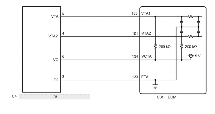
| *a | Throttle Position Sensor (Throttle Body Assembly) |
CAUTION / NOTICE / HINT
Note
-
Vehicle Control History may be stored in the hybrid vehicle control ECU if the engine is malfunctioning. Certain vehicle condition information is recorded when Vehicle Control History is stored. Reading the vehicle conditions recorded in both the freeze frame data and Vehicle Control History can be useful for troubleshooting.
(Select Powertrain in Health Check and then check the time stamp data.)
-
If any "Engine Malfunction" Vehicle Control History item has been stored in the hybrid vehicle control ECU, make sure to clear it. However, as all Vehicle Control History items are cleared simultaneously, if any Vehicle Control History items other than "Engine Malfunction" are stored, make sure to perform any troubleshooting for them before clearing Vehicle Control History.
Tech Tips
Read freeze frame data using the GTS. The ECM records vehicle and driving condition information as freeze frame data the moment a DTC is stored. When troubleshooting, freeze frame data can help determine if the vehicle was moving or stationary, if the engine was warmed up or not, if the air fuel ratio was lean or rich, and other data from the time the malfunction occurred.
PROCEDURE
-
READ VALUE USING GTS (THROTTLE POSITION SENSOR NO.1 VOLTAGE)
-
Connect the GTS to the DLC3.
-
Turn the power switch on (IG).
-
Turn the GTS on.
-
Enter the following menus: Powertrain / Engine / Data List / Throttle Position Sensor No.1 Voltage.
Powertrain > Engine > Data ListTester Display Throttle Position Sensor No.1 Voltage -
Read the values displayed on the GTS.
-
Disconnect the throttle body assembly connector.
-
Compare the value of the Data List item Throttle Position Sensor No. 1 Voltage after disconnecting the throttle body assembly connector to the value when the connector was connected.
Result Result Proceed to Changes from less than 0.56 V to higher than 4.535 V A Does not change from less than 0.56 V B
A 
REPLACE THROTTLE BODY ASSEMBLY Click here
B 
-
-
CHECK HARNESS AND CONNECTOR (THROTTLE POSITION SENSOR - ECM)
-
Disconnect the throttle body assembly connector.
-
Disconnect the ECM connector.
-
Measure the resistance according to the value(s) in the table below.
Standard Resistance Tester Connection Condition Specified Condition C4-5 (VC) - C31-134 (VCTA) Always Below 1 Ω C4-6 (VTA) or C31-135 (VTA1) - Body ground and other terminals Always 10 kΩ or higher Result Proceed to OK NG
OK
REPLACE ECM Click here
NG
REPAIR OR REPLACE HARNESS OR CONNECTOR
-