ENTRY AND START SYSTEM(for Start Function) Power Source Mode does not Change to ON (READY)
DESCRIPTION
When the electrical key transmitter sub-assembly is in the cabin and the power switch is pressed, the certification ECU (smart key ECU assembly) receives a signal and changes the power source mode. Additionally, when park (P) selected and the brake pedal is depressed, the hybrid control system can be started by pressing the power switch. If the steering is unlocked, the hybrid control system can also be started by pressing the power switch with park (P) selected and the brake pedal depressed.
| Problem Symptom | Data List and Active Test |
|---|---|
| Power source mode does not change to ON (READY) |
Power Source Control
Entry&Start |
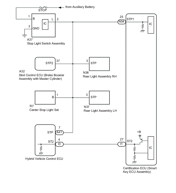
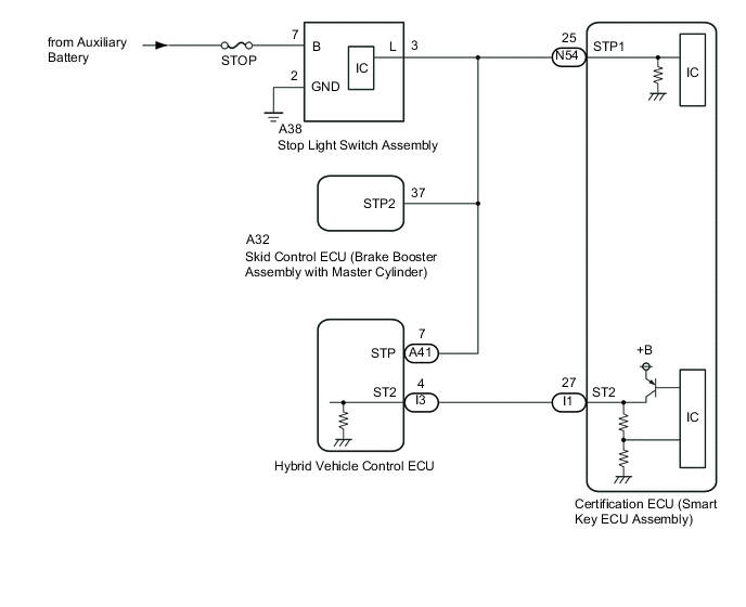
WIRING DIAGRAM
-
w/ Canister Pump Module
-
w/o Canister Pump Module
CAUTION / NOTICE / HINT
Note
-
When using the GTS with the power switch off, connect the GTS to the DLC3 and turn a courtesy light switch on and off at intervals of 1.5 seconds or less until communication between the GTS and the vehicle begins. Then select Model Code "KEY REGIST" under manual mode and enter the following menus: Body Electrical / Entry&Start(CAN). While using the GTS, periodically turn a courtesy light switch on and off at intervals of 1.5 seconds or less to maintain communication between the GTS and the vehicle.
-
The entry and start system (for Start Function) uses the LIN communication system and CAN communication system. Inspect the communication function by following How to Proceed with Troubleshooting. Troubleshoot the entry and start system (for Start Function) after confirming that the communication systems are functioning properly.
-
If the entry and start system (for Start Function) has been canceled, enable the system before performing troubleshooting.
-
Inspect the fuses of circuits related to this system before performing the following procedure.
-
Before replacing the certification ECU (smart key ECU assembly) or an electrical key transmitter sub-assembly, refer to entry and start system (for Start Function) Precaution.
-
After completing repairs, confirm that the problem does not recur.
Tech Tips
When the cable is disconnected and reconnected to the negative (-) auxiliary battery terminal, the power source mode returns to the state it was in before the cable was disconnected.
PROCEDURE
-
CHECK ELECTRICAL KEY TRANSMITTER SUB-ASSEMBLY
-
Press a switch of the electrical key transmitter sub-assembly.
OK The electrical key transmitter sub-assembly LED illuminates. Result Proceed to OK NG
NG 
INSPECT TRANSMITTER BATTERY Click here
OK 
-
-
READ VALUE USING GTS (KEY LOW BATTERY)
-
Connect the GTS to the DLC3.
-
Turn the power switch on (IG).
-
Turn the GTS on.
-
Enter the following menus: Body Electrical / Entry&Start / Data List.
-
Read the Data List according to the display on the GTS.
Body Electrical > Entry&Start > Data ListTester Display Measurement Item Range Normal Condition Diagnostic Note Key Low Battery Transmitter battery depleted No or Yes No: Transmitter battery not depleted
Yes: Transmitter battery depleted
The electrical key transmitter sub-assembly sends voltage information to the certification ECU (smart key ECU assembly) when it is transmitting. "Yes" is displayed for the Data List item "Key Low Battery" when this voltage information indicates 2.2 V or less. This Data List item should be checked when the electrical key transmitter sub-assembly is at room temperature (example: at -20°C (-4°F), "Yes" may be displayed even if the transmitter battery is new).
Body Electrical > Entry&Start > Data ListTester Display Key Low Battery Result Result Proceed to "No" is displayed on the GTS screen A "Yes" is displayed on the GTS screen B
B 
REPLACE TRANSMITTER BATTERY Click here
A
-
-
CHECK WAVE ENVIRONMENT
-
If the problem occurs in certain locations or times of day, the possibility of wave interference is high.
Tech Tips
Whether the problem is due to wave interference can be checked by holding the electrical key transmitter sub-assembly near the door control receiver.
OK Power source mode changes to on (READY). Result Proceed to OK NG
OK
AFFECTED BY WAVE INTERFERENCE
NG
-
-
CHECK POWER SWITCH CONDITION
-
Get into the vehicle while carrying an electrical key transmitter sub-assembly.
-
Check that park (P) is selected.
-
With the brake pedal released, check that pressing the power switch causes the power source mode to change.
Result Result Proceed to Power source mode changes : Off → on (ACC) → on (IG) → off A Power source mode does not change to on (ACC) or on (IG) B Power source mode changes to on (IG) but not to on (ACC) C Power source mode changes to on (ACC) but not to on (IG) D
B
GO TO POWER SOURCE MODE DOES NOT CHANGE TO ON (IG AND ACC) Click here
C
GO TO POWER SOURCE MODE DOES NOT CHANGE TO ON (ACC) Click here
D
GO TO POWER SOURCE MODE DOES NOT CHANGE TO ON (IG) Click here
A
-
-
READ VALUE USING GTS (SHIFT POSITION P)
-
Connect the GTS to the DLC3.
-
Turn the power switch on (IG).
-
Turn the GTS on.
-
Enter the following menus: Body Electrical / Power Source Control / Data List.
-
Read the Data List according to the display on the GTS.
Body Electrical > Power Source Control > Data ListTester Display Measurement Item Range Normal Condition Diagnostic Note Shift P Signal Pulse P position signal status Normal1, Normal2, Normal3, Error1, Error2, Error3 or Unknown Normal1: Signal normal and park (P) state cannot be determined
Normal2: Signal normal and park (P) selected
Normal3: Signal normal and R, N, D or B selected
Error1: Signal abnormal and park (P) state cannot be determined
Error2: Signal abnormal and park (P) selected
Error3: Signal abnormal and R, N, D or B selected
Unknown: Other
Use this item to determine if the P position signal is malfunctioning.
Body Electrical > Power Source Control > Data ListTester Display Shift P Signal Pulse OK The GTS display changes correctly in response to the shift lever operation. Result Proceed to OK NG
NG
GO TO HYBRID CONTROL SYSTEM (HOW TO PROCEED WITH TROUBLESHOOTING) Click here
OK
-
-
CHECK FOR DTC
-
Using the GTS, check for certification ECU (smart key ECU assembly) DTCs.
Body Electrical > Entry&Start > Trouble Codes
Body Electrical > Power Source Control > Trouble CodesResult Result Proceed to DTCs are not output A Entry and start system (for Start Function) DTCs are output B
B
GO TO DIAGNOSTIC TROUBLE CODE CHART Click here
A
-
-
READ VALUE USING GTS (STOP LIGHT SWITCH1)
-
Connect the GTS to the DLC3.
-
Turn the power switch on (IG).
-
Turn the GTS on.
-
Enter the following menus: Body Electrical / Power Source Control / Data List.
-
Read the Data List according to the display on the GTS.
Body Electrical > Power Source Control > Data ListTester Display Measurement Item Range Normal Condition Diagnostic Note Stop Light Switch1 State of brake pedal OFF or ON OFF: Brake pedal released
ON: Brake pedal depressed
-
Use this item to determine if the stop light switch assembly is malfunctioning.
-
The hybrid control system cannot be started when this item is OFF.
-
If the stop light switch assembly is malfunctioning, the hybrid control system can be started by pressing and holding the power switch for a certain period of time.
Body Electrical > Power Source Control > Data ListTester Display Stop Light Switch1 OK The GTS display changes correctly in response to the brake pedal operation. Result Proceed to OK NG -
NG
CHECK HARNESS AND CONNECTOR (CERTIFICATION ECU (SMART KEY ECU ASSEMBLY) - POWER SUPPLY AND BODY GROUND) Click here
OK
-
-
READ VALUE USING GTS (STARTER REQUEST SIGNAL)
-
Connect the GTS to the DLC3.
-
Turn the power switch on (IG).
-
Turn the GTS on.
-
Enter the following menus: Body Electrical / Power Source Control / Data List.
-
Read the Data List according to the display on the GTS.
Body Electrical > Power Source Control > Data ListTester Display Measurement Item Range Normal Condition Diagnostic Note Starter Request Signal Hybrid control system start request signal status OFF or ON OFF: The power switch is not pressed
ON: With the park (P) selected and the brake pedal depressed, the power switch is pressed and held
-
When the hybrid control system cannot be started due to a start request signal malfunction, OFF is displayed.
-
When the power switch is pressed, the duration of time that ON is displayed will be extremely short. As such, the power switch needs to be pressed and held for a certain period of time.
Body Electrical > Power Source Control > Data ListTester Display Starter Request Signal Note
Check that the key indicator display is displayed on the multi-information display in the combination meter assembly, and then press the power switch.
OK The GTS display changes correctly in response to the power switch operation. Result Proceed to OK NG -
NG
CHECK PARKING LOCK MECHANISM Click here
OK
-
-
CHECK HARNESS AND CONNECTOR (CERTIFICATION ECU (SMART KEY ECU ASSEMBLY) - HYBRID VEHICLE CONTROL ECU)
-
Disconnect the I1 certification ECU (smart key ECU assembly) connector.
-
Disconnect the I3 hybrid vehicle control ECU connector.
-
Measure the resistance according to the value(s) in the table below.
Standard Resistance Tester Connection Condition Specified Condition I1-27 (ST2) - I3-4 (ST2) Always Below 1 Ω I1-27 (ST2) or I3-4 (ST2) - Body ground Always 10 kΩ or higher Result Proceed to OK NG
NG
REPAIR OR REPLACE HARNESS OR CONNECTOR
OK
-
-
CHECK CERTIFICATION ECU (SMART KEY ECU ASSEMBLY)
-
Reconnect the I1 certification ECU (smart key ECU assembly) connector.
-
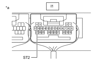
*a Component with harness connected
(Certification ECU (Smart Key ECU Assembly))
Measure the voltage according to the value(s) in the table below.
Standard Voltage Tester Connection Condition Specified Condition I1-27 (ST2) - Body ground Power switch pressed and held with brake pedal depressed (starter on) → Approximately 1 second after power switch released (starter off) 8.5 V or higher → 1.0 V or less Result Proceed to OK NG
OK
GO TO HYBRID CONTROL SYSTEM (HOW TO PROCEED WITH TROUBLESHOOTING) Click here
NG
REPLACE CERTIFICATION ECU (SMART KEY ECU ASSEMBLY)
-
-
INSPECT TRANSMITTER BATTERY
-
Inspect the transmitter battery.
Note
Do not wrap the lead wire ground a terminal, wedge it between terminals, or solder it. The terminal may be deformed or damaged, and the transmitter battery will not be able to be installed correctly.
Result Proceed to OK NG
OK
REPLACE ELECTRICAL KEY TRANSMITTER SUB-ASSEMBLY
NG
REPLACE TRANSMITTER BATTERY Click here
-
-
CHECK PARKING LOCK MECHANISM
-
Turn the power switch on (IG).
-
With park (P) selected, select neutral (N).
-
Check that the shift position indicator on the combination meter assembly indicates neutral (N).
Tech Tips
With park (P) selected, the shift state can only be changed to neutral (N) when the parking lock mechanism is unlocked.
OK The shift position indicator indicates neutral (N). Result Proceed to OK NG
NG
GO TO ELECTRONIC SHIFT LEVER SYSTEM Click here
OK
-
-
CHECK SECURITY INDICATOR LIGHT (IMMOBILISER SYSTEM UNSET)
-
Get into the vehicle while carrying an electrical key transmitter sub-assembly.
-
Check that park (P) is selected.
-
Press the power switch with the brake pedal released and check that the security indicator light changes from blinking to off at the same time that the power source mode changes to on (ACC).
Tech Tips
The immobiliser function can be determined to be operating correctly if the security indicator light changes from blinking to off at the same time that the power source mode changes to on (ACC).
OK The security indicator light changes from blinking to off at the same time that the power source mode changes to on (ACC). Result Proceed to OK NG
OK
REPLACE CERTIFICATION ECU (SMART KEY ECU ASSEMBLY)
NG
GO TO IMMOBILISER SYSTEM (PROBLEM SYMPTOMS TABLE) Click here
-
-
CHECK HARNESS AND CONNECTOR (CERTIFICATION ECU (SMART KEY ECU ASSEMBLY) - POWER SUPPLY AND BODY GROUND)
-
w/ Canister Pump Module
-
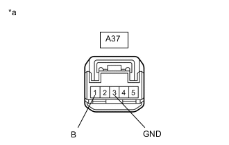
*a Front view of wire harness connector
(to Stop Light Switch Assembly)
Disconnect the A37 stop light switch assembly connector.
-
Measure the voltage according to the value(s) in the table below.
Standard Voltage Tester Connection Condition Specified Condition A37-1 (B) - Body ground Power switch off 11 to 14 V -
Measure the resistance according to the value(s) in the table below.
Standard Resistance Tester Connection Condition Specified Condition A37-3 (GND) - Body ground Always Below 1 Ω
-
-
w/o Canister Pump Module
-
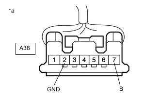
*a Front view of wire harness connector
(to Stop Light Switch Assembly)
Disconnect the A38 stop light switch assembly connector.
-
Measure the voltage according to the value(s) in the table below.
Standard Voltage Tester Connection Condition Specified Condition A38-7 (B) - Body ground Power switch off 11 to 14 V -
Measure the resistance according to the value(s) in the table below.
Standard Resistance Tester Connection Condition Specified Condition A38-2 (GND) - Body ground Always Below 1 Ω
Result Proceed to OK NG -
NG
REPAIR OR REPLACE HARNESS OR CONNECTOR
OK
-
-
CHECK HARNESS AND CONNECTOR (CERTIFICATION ECU (SMART KEY ECU ASSEMBLY) - STOP LIGHT SWITCH ASSEMBLY)
-
Disconnect the N54 certification ECU (smart key ECU assembly) connector.
-
Disconnect the A41 hybrid vehicle control ECU connector.
-
Disconnect the A32 skid control ECU (brake booster assembly with master assembly) connector.
-
Disconnect the N36 rear light assembly RH connector.*
-
Disconnect the N37 rear light assembly LH connector.*
-
Disconnect the R7 center stop light set connector.*
-
*: w/ Canister Pump Module
-
-
Measure the resistance according to the value(s) in the table below.
Standard Resistance w/ Canister Pump Module Tester Connection Condition Specified Condition N54-25 (STP1) - A37-2 (L) Always Below 1 Ω N54-25 (STP1) or A37-2 (L) - Body ground Always 10 kΩ or higher A37-3 (GND) - Body ground Always Below 1 Ω w/o Canister Pump Module Tester Connection Condition Specified Condition N54-25 (STP1) - A38-3 (L) Always Below 1 Ω N54-25 (STP1) or A38-3 (L) - Body ground Always 10 kΩ or higher A38-2 (GND) - Body ground Always Below 1 Ω Result Proceed to OK NG
NG
REPAIR OR REPLACE HARNESS OR CONNECTOR
OK
-
-
INSPECT STOP LIGHT SWITCH ASSEMBLY
-
Inspect the stop light switch assembly.
Result Proceed to OK NG
OK
REPLACE CERTIFICATION ECU (SMART KEY ECU ASSEMBLY)
NG
REPLACE STOP LIGHT SWITCH ASSEMBLY Click here
-