FC CONTROL SYSTEM UTILITY
-
Check Mode (Air System Component Inspection)
If the actual air pressure that is measured by the pressure sensor has abnormally deviated from an estimated air pressure that is based on the motor speed of the FC air compressor and the condition of the regulated air pressure regulating valve and air shunt valve, the air system component inspection will interpret it that malfunctions has occurred somewhere in the air system components including the air pipes, and set DTCs.
Figure 1. Air system circuit
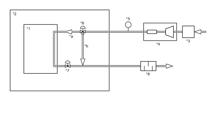
*1 FC Stack *2 FC Stack Assembly *3 Mass Air Flow Meter *4 FC Air Compressor with Motor Assembly *5 FC Stack Inlet Air Pressure Sensor (Turbo Pressure Sensor) *6 Air Shunt Valve *7 Air Pressure Regulating Valve *8 FC Exhaust Tail Pipe Assembly *a To the FC stack *b To the FC stack bypass Note
-
As the airflow volume will be decreased at areas of high elevation, the check mode (air system component inspection) judgment result will not be accurate. For this reason, check mode (air system component inspection) judgment should be performed at elevations below 1000 m (3280 ft.). If a DTC is output, use the pressure waveform data during testing to evaluate the results.
-
Conduct air system component inspection when "Smoothed Value of FC Stack Coolant Temperature (FC Stack Outlet)" in the Data List is over 10°C (50°F).
-
The inspection result is determined by checking the DTC output and waveform during testing.
Tech Tips
By entering check mode using a GTS, the following inspections can be conducted without removing the components; the air system component operations (air shunt valve, air pressure regulating valve), and blockage and leakage of the air system pipes.
-
Check that the shift lever is in P.
-
Connect the GTS to the DLC3.
-
Turn the power switch on (IG).
-
Turn the GTS on.
-
Clear the FC system DTC(s).
-
Enter the following menus: Powertrain / FC / Utility / Check Mode.
Powertrain > FC > UtilityTester Display Check Mode Note
-
When changing between modes, the stored DTC and freeze frame data is erased, so save the detected data before changing modes.
-
Changing from normal mode to check mode function is not available when the power switch is turned on (READY).
-
-
Enter the following menus: Powertrain / FC / Data List / Smoothed Value of FC Stack Air Pressure (FC Stack Inlet), Target Air Pressure Regulating Valve Position, Target Air Shunt Valve Position, Air Compressor Revolution
Powertrain > FC > Data ListTester Display Smoothed Value of FC Stack Air Pressure (FC Stack Inlet) Target Air Pressure Regulating Valve Position Target Air Shunt Valve Position Air Compressor Revolution -
During check mode (air system component inspection), use the Snapshot function of the GTS to record the values of the Data List items listed above.
-
Turn the power switch on (READY).
Note
The following conditions must be met for the Air System Component Inspection. If any one of the conditions is not met during inspection, the ongoing inspection will be canceled, and it will restart from the beginning when all conditions are satisfied again.
-
Shift lever in P
-
Power switch on (READY)
-
Air system component inspection is not yet completed
-
-
Wait for 5 minutes.
Note
A GTS shows no indication that air system component inspection has finished.
-
Enter the following menus: Powertrain / FC / Trouble Codes.
-
Check for DTCs.
Powertrain > FC > Trouble Codes -
Check the data obtained during Check Mode (Air System Component Inspection), which was recorded with the snapshot.
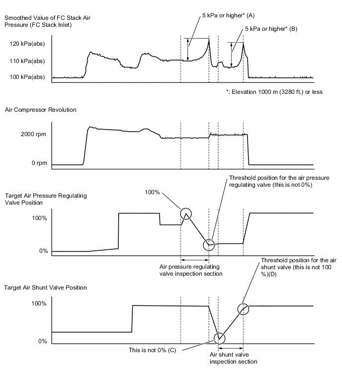
Figure 2. Reference waveforms obtained during Check Mode (Air System Component Inspection)
Tech Tips
-
The operation of the air pressure regulating valve is checked by referring to variation (A) that occurs when the valve operates from open to close with the air passage of the air shunt valve fixed (100% to the FC stack side).
-
The operation of the air shunt valve is checked by referring to variation (B) that occurs when the air passage direction of the valve switches from the stack bypass side (C) to the FC stack side (D) with the air pressure regulating valve opening angle fixed (15 to 20%).
-
-