GLOW PLUG REMOVAL
CAUTION / NOTICE / HINT
CAUTION:
-
To prevent burns, do not touch the engine, exhaust manifold or other high temperature components while the engine is hot.
-
To prevent burns, do not touch the engine, exhaust pipe or other high temperature components while the engine is hot.
-
Make sure to wear protective gloves when performing work to avoid burns.
Note
-
When replacing the parts in the following chart (A), replace the No. 1 injection pipe sub-assembly, No. 2 injection pipe sub-assembly and/or fuel inlet pipe sub-assembly with new ones.
Replaced Parts (A) Pipes Requiring New Replacement
-
Common rail assembly
-
No. 1 injection pipe sub-assembly
-
No. 2 injection pipe sub-assembly
-
Fuel inlet pipe sub-assembly
-
-
After removing the No. 1 injection pipe sub-assembly, No. 2 injection pipe sub-assembly and/or fuel inlet pipe sub-assembly, clean them with a brush and compressed air.
-
The common rail assembly is a precision instrument. Do not use the common rail assembly if it is struck or dropped.
-
Hold the common rail assembly itself during removal and installation. Do not hold the pressure discharge valve or fuel pressure sensor, etc.
-
Make sure foreign matter does not enter the fuel path.
PROCEDURE
-
WARM UP ENGINE
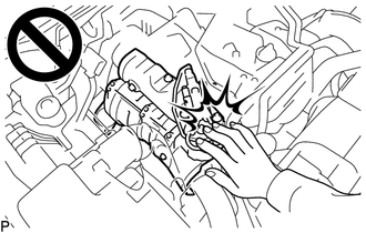
CAUTION:
To protect the glow plug assembly from damage, before removing the glow plug assembly, make sure to warm up the engine.
-
REMOVE COMMON RAIL ASSEMBLY
-
REMOVE NO. 1 GLOW PLUG CONNECTOR
CAUTION:
Make sure to wear protective gloves when performing work to avoid burns.
-
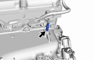
Using an E8 "TORX" socket wrench, remove the stud bolt from the intake manifold.
-
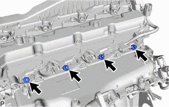
Remove the 4 glow plug screw grommets.
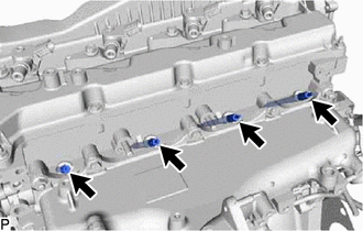
-
Remove the 4 nuts and No. 1 glow plug connector.
-
-
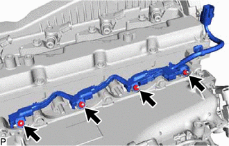
REMOVE GLOW PLUG ASSEMBLY
CAUTION:
Make sure to wear protective gloves when performing work to avoid burns.
-
Using a 10 mm deep socket wrench, remove the 4 glow plug assemblies.
-