CYLINDER BLOCK DISASSEMBLY
PROCEDURE
-
INSPECT CONNECTING ROD SUB-ASSEMBLY THRUST CLEARANCE
-
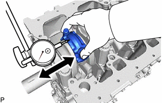
Using a dial indicator, measure the thrust clearance while moving the connecting rod sub-assembly back and forth.
Standard thrust clearance 0.10 to 0.45 mm (0.00394 to 0.0177 in.) Maximum thrust clearance 0.45 mm (0.0177 in.) If the thrust clearance is more than the maximum, replace the connecting rod sub-assembly. If necessary, replace the crankshaft.
-
-
INSPECT CONNECTING ROD SUB-ASSEMBLY OIL CLEARANCE
-
Remove the 2 connecting rod bolts.
-
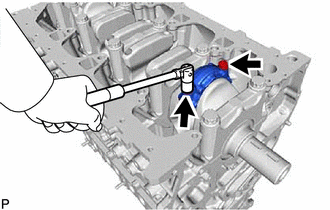
Using the 2 removed connecting rod bolts, move the connecting rod cap back and forth to remove the connecting rod cap from the connecting rod sub-assembly.
Tech Tips
Keep the connecting rod bearing and connecting rod cap together.
-
Clean the crank pin and connecting rod bearing.
-
Check the crank pin and connecting rod bearing for pitting and scratches.
If the crank pin or connecting rod bearing is damaged, replace the connecting rod bearings. If necessary, replace the crankshaft.
-
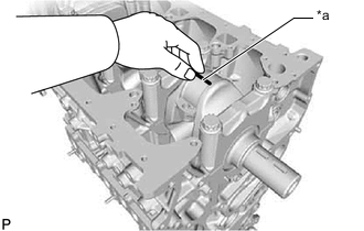
*a Plastigage Lay a strip of Plastigage on the crank pin.
-
Install the connecting rod cap to the connecting rod sub-assembly.
Note
Do not turn the crankshaft.
-
Remove the 2 connecting rod bolts and connecting rod cap from the connecting rod sub-assembly.
Tech Tips
Keep the connecting rod bearing and connecting rod cap together.
-
Measure the Plastigage at its widest point.
Standard oil clearance 0.042 to 0.048 mm (0.00165 to 0.00189 in.) Maximum oil clearance 0.054 mm (0.00213 in.) Note
Remove the Plastigage completely after the measurement.
If the oil clearance is more than the maximum, replace the connecting rod bearing. If necessary, grind or replace the crankshaft.
Tech Tips
If using a standard connecting rod bearing, replace it with one that has the same number. If the number of the connecting rod bearing cannot be determined, select the correct connecting rod bearing by adding together the numbers imprinted on the crankshaft and connecting rod cap, and then selecting the connecting rod bearing with the same number as the total. There are 5 sizes of standard connecting rod bearings, marked 2, 3, 4, 5 and 6.
EXAMPLE:
Connecting rod cap (A) "3" + Crankshaft (B) "1" = Total number 4 (Use connecting rod bearing (C) "4")
Connecting Rod Cap (A) Crankshaft (B) Use Connecting Rod Bearing (C) 1 1 2 2 3 3 4 2 1 3 2 4 3 5 3 1 4 2 5 3 6 Standard Connecting Rod Sub-assembly Big End Inside Diameter (A) Item Specified Condition Mark 1 58.014 to 58.020 mm (2.2840 to 2.2842 in.) Mark 2 58.020 to 58.026 mm (2.2842 to 2.2845 in.) Mark 3 58.026 to 58.032 mm (2.2845 to 2.2847 in.) Standard Crank Pin Diameter (B) Item Specified Condition Mark 1 54.994 to 55.000 mm (2.1651 to 2.1654 in.) Mark 2 54.988 to 54.994 mm (2.1649 to 2.1651 in.) Mark 3 54.982 to 54.988 mm (2.1646 to 2.1649 in.) Standard Sized Connecting Rod Bearing Center Wall Thickness (C) Item Specified Condition Mark 2 1.486 to 1.489 mm (0.0585 to 0.0586 in.) Mark 3 1.489 to 1.492 mm (0.0586 to 0.0587 in.) Mark 4 1.492 to 1.495 mm (0.0587 to 0.0589 in.) Mark 5 1.495 to 1.498 mm (0.0589 to 0.0590 in.) Mark 6 1.498 to 1.501 mm (0.0590 to 0.0591 in.) 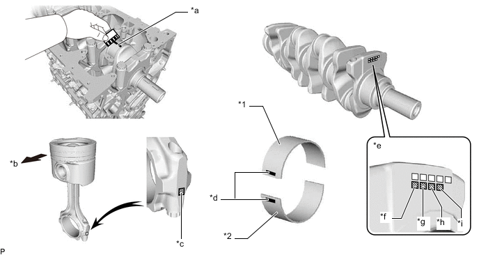
*1 No. 1 Connecting Rod Bearing *2 No. 2 Connecting Rod Bearing *a Plastigage *b Front Side *c Connecting Rod Sub-assembly Big End Inside Diameter:
Mark 1, 2 or 3
*d Connecting Rod Bearing:
Mark 2, 3, 4, 5 or 6
*e Crank Pin Diameter:
Mark 1, 2 or 3
*f No. 1 *g No. 2 *h No. 3 *i No. 4 - - -
Completely remove the Plastigage from the crank pin.
-
-
REMOVE PISTON AND CONNECTING ROD SUB-ASSEMBLY
-
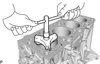
Using a ridge reamer, remove all the carbon from the top of the cylinder.
-
Push out the piston and connecting rod sub-assembly with connecting rod bearing through the top of the cylinder block sub-assembly to remove them.
Tech Tips
-
Keep the connecting rod sub-assembly and connecting rod cap together.
-
Arrange the piston and connecting rod sub-assemblies in the correct order.
-
Be sure to arrange the removed piston and connecting rod sub-assemblies in such a way that they can be reinstalled exactly as before.
-
-
-
REMOVE CONNECTING ROD BEARING
-
Remove the No. 1 connecting rod bearings and No. 2 connecting rod bearings from the connecting rod sub-assemblies and connecting rod caps.
Tech Tips
Arrange the removed parts in the correct order.
-
-
REMOVE PISTON RING SET
Tech Tips
Arrange the piston rings in the correct order.
-
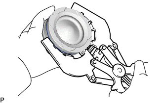
Using a piston ring expander, remove the No. 1 compression ring and No. 2 compression ring from the piston.
-
Using a piston ring expander, remove the oil ring rail from the piston.
-
Remove the oil ring expander from the piston by hand.
-
-
REMOVE PISTON WITH PIN SUB-ASSEMBLY
-
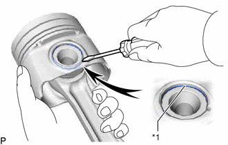
*1 Piston Pin Hole Snap Ring Using a small screwdriver, pry out the front side piston pin hole snap ring from the piston.
-
Gradually heat the piston to approximately 80°C (176°F).
CAUTION:
Be sure to wear protective gloves.
-
Using a plastic-faced hammer and brass bar, lightly tap out the piston pin from the piston. Then remove the connecting rod sub-assembly.
Tech Tips
-
The piston and piston pin are a matched set.
-
Be sure to organize the removed pistons, piston pins, piston rings, connecting rod sub-assemblies and connecting rod bearings in such a way that the parts can be reinstalled exactly as before.
-
Arrange the pistons, piston pins, connecting rod sub-assemblies and connecting rod bearings in the correct order.
-
-
-
INSPECT CRANKSHAFT THRUST CLEARANCE
-
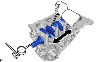
Using a dial indicator, measure the crankshaft thrust clearance while prying the crankshaft back and forth with a screwdriver.
Standard thrust clearance 0.04 to 0.24 mm (0.00157 to 0.00945 in.) Maximum thrust clearance 0.24 mm (0.00945 in.) If the thrust clearance is more than the maximum, replace the upper crankshaft thrust washers and lower crankshaft thrust washers. If necessary, replace the crankshaft.
Standard crankshaft thrust washer thickness 2.2 to 2.8 mm (0.0866 to 0.110 in.)
-
-
REMOVE CRANKSHAFT
-
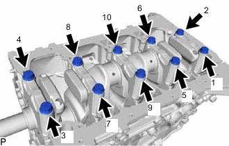
Using several steps, uniformly loosen and remove the 10 crankshaft bearing cap set bolts in the sequence shown in the illustration.
-
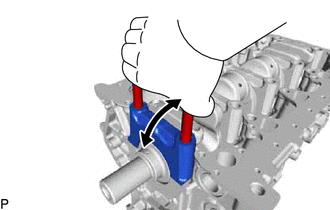
Using the removed crankshaft bearing cap set bolts, pry the crankshaft bearing cap back and forth and remove the crankshaft bearing caps, No. 2 crankshaft bearings and lower crankshaft thrust washers (No. 5 crankshaft journal only).
Tech Tips
-
Keep the No. 2 crankshaft bearing and crankshaft bearing cap together.
-
Be sure to organize the crankshaft bearing caps and lower crankshaft thrust washers (No. 5 crankshaft journal only) in such a way that they can be reinstalled exactly as before.
-
-
Remove the crankshaft from the cylinder block sub-assembly.
-
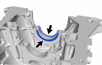
Remove the 2 upper crankshaft thrust washers (No. 5 cylinder block sub-assembly journal only) from the cylinder block sub-assembly.
Tech Tips
Arrange the upper crankshaft thrust washers in the correct order.
-
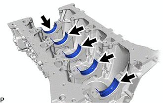
Remove the 5 No. 1 crankshaft bearings from the cylinder block sub-assembly.
Tech Tips
Arrange the No. 1 crankshaft bearings in the correct order.
-
Check each crankshaft journal, No. 1 crankshaft bearings and No. 2 crankshaft bearings for pitting and scratches.
If the journal or crankshaft bearing is damaged, replace the crankshaft bearings. If necessary, replace the crankshaft.
-
-
REMOVE NO. 1 OIL NOZZLE SUB-ASSEMBLY
-
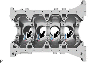
Using a 5 mm hexagon wrench, remove the 4 bolts and 4 No. 1 oil nozzle sub-assemblies from the cylinder block sub-assembly.
-
-
REMOVE CYLINDER BLOCK WATER DRAIN COCK SUB-ASSEMBLY
-
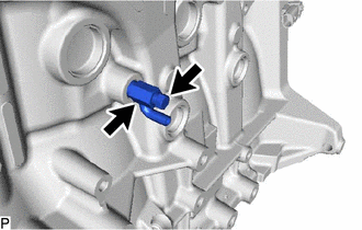
Remove the cylinder block water drain cock plug from the cylinder block water drain cock sub-assembly.
-
Remove the cylinder block water drain cock sub-assembly from the cylinder block sub-assembly.
-
-
REMOVE STUD BOLT
Note
If a stud bolt is deformed or its threads are damaged, replace it.