ANTI-LOCK BRAKE SYSTEM, Diagnostic DTC:C1425

| DTC Code | DTC Name |
|---|---|
| C1425 | Open in Stop Light Switch Circuit |
DESCRIPTION
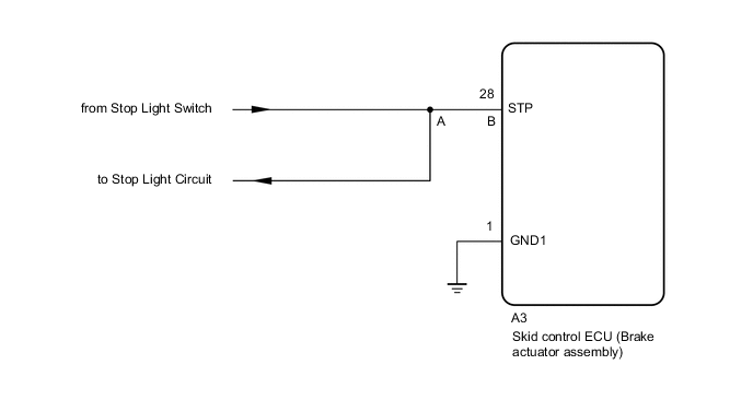
The skid control ECU (brake actuator assembly) detects the brake operating conditions through a signal transmitted by the stop light switch.
The skid control ECU (brake actuator assembly) has an open detection circuit, which outputs this DTC when detecting an open in the stop light input line or the ground line of the stop light circuit with the stop light switch off (brake pedal not depressed).
| DTC No. | Detection Item | DTC Detection Condition | Trouble Area |
|---|---|---|---|
| C1425 | Open in Stop Light Switch Circuit | When voltage at terminal IG1 is 9.5 to 17.4 V, open circuit occurs between STP terminal circuits A and B for 0.3 seconds or more. |
|
WIRING DIAGRAM
CAUTION / NOTICE / HINT
Note
When replacing the skid control ECU (brake actuator assembly), perform Test Mode (Signal Check) to acquire the rear differential lock identification information.
PROCEDURE
-
CHECK STOP LIGHT OPERATION
-
Check that all the stop lights come on when the brake pedal is depressed, and go off when the brake pedal is released.
OK Condition Illumination Condition Brake pedal depressed ON Brake pedal released OFF Result Proceed to OK NG
NG 
CHECK STOP LIGHT CIRCUIT Click here
OK 
-
-
CHECK TERMINAL VOLTAGE (STP TERMINAL)
-
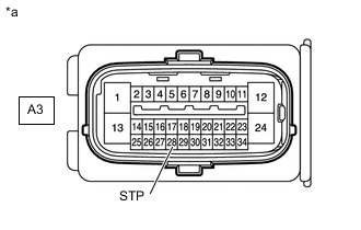
*a Front view of wire harness connector
(to Skid Control ECU [Brake Actuator Assembly])
Turn the ignition switch off.
-
Make sure that there is no looseness at the locking part and the connecting part of the connectors.
-
Disconnect the A3 skid control ECU (brake actuator assembly) connector.
-
Measure the voltage according to the value(s) in the table below.
Standard Voltage Tester Connection Switch Condition Specified Condition A3-28 (STP) - Body ground Stop light switch ON (Brake pedal depressed) 8 to 14 V Stop light switch OFF (Brake pedal released) Below 1.5 V Result Proceed to OK NG
NG
REPAIR OR REPLACE HARNESS OR CONNECTOR (BRAKE ACTUATOR ASSEMBLY - STOP LIGHT CIRCUIT)
OK
-
-
RECONFIRM DTC
-
Turn the ignition switch off.
-
Reconnect the A3 skid control ECU (brake actuator assembly) connector.
-
Clear the DTCs.
Chassis > ABS/VSC/TRC > Clear DTCs -
Turn the ignition switch off.
-
Start the engine.
-
Depress the brake pedal several times to test the stop light circuit.
-
Check if the same DTC is recorded.
Chassis > ABS/VSC/TRC > Trouble CodesTech Tips
If troubleshooting has been carried out according to the Problem Symptoms Table, refer back to the table and proceed to the next step.
Result Proceed to DTC C1425 is not output DTC C1425 is output
DTC C1425 is not output
USE SIMULATION METHOD TO CHECK Click here
DTC C1425 is output
REPLACE BRAKE ACTUATOR ASSEMBLY Click here
-