INTEGRATION RELAY ON-VEHICLE INSPECTION

-
INSPECT ENGINE ROOM JUNCTION BLOCK ASSEMBLY (SIGNAL READING CHECK)
Note
Both present and history signal readings will be cleared if the engine room junction block assembly is removed. Make sure not to remove it before inspection.
Tech Tips
The signal readings of the engine room junction block assembly can be checked by inspecting the voltage at the diagnosis terminal.
-
Signal reading check
-
Turn the engine switch on (IG).
-
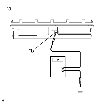
Text in Illustration *a Component with harness connected
(Engine Room Junction Block Assembly)
*b Diagnosis Terminal Connect the positive (+) terminal of a voltmeter to the engine room junction block assembly and the negative (-) terminal to the body ground.
-
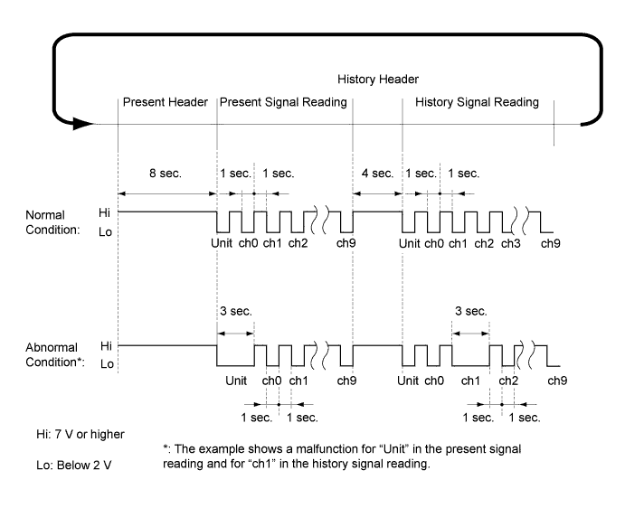
Using the illustration below as a reference, determine whether any channels are malfunctioning based on the observed signal reading.
Tech Tips
-
Present signal reading and history signal reading will be displayed alternately after the engine switch is turned to on (IG). By measuring the duration of each header, the present signal reading and history signal reading can be recognized.
-
A unit malfunction indicates an internal malfunction of the engine room junction block assembly. If a malfunction is detected for any channel from channel 0 to 9, an electrical load connected to the engine room junction block assembly may be malfunctioning or there may be a short in the engine room junction block assembly circuit or in the wire harness.
-
The present signal reading will be stored as a history signal reading when electrical loads are operated after a malfunctioning part returns to normal.
-
Both present and history signal readings can be cleared by disconnecting the cable from the negative (-) battery terminal.
-
Regarding electrical loads connected to channels 0 to 9, refer to the table below:
Channel Connected Electrical Load for 2GR-FE for 2AR-FE w/ Rear Fog Light or w/ Mirror Heater w/o Rear Fog Light and w/o Mirror Heater ch0 Magnetic clutch Radiator fan motor Radiator fan motor ch1 - Condenser fan motor Condenser fan motor ch2 Stop lights ch3 Rear fog lights Rear fog lights - ch4 Daytime running lights ch5 Front fog lights ch6 Rear window defogger wire ch7 - Mirror heater - ch8 High beam headlight LH ch9 High beam headlight RH
-
-
-
-
INSPECT ENGINE ROOM JUNCTION BLOCK ASSEMBLY (RESULTS OF SIGNAL READING CHECK)
-
Results of signal reading check
-
Depending on the signal reading, perform troubleshooting according the table below.
Output Signal Reading Repair Method Normal Continue troubleshooting for each system. The unit is malfunctioning. Replace the engine room junction block. A malfunction in a channel (ch0 to ch9)
-
Check for a short in the wire harnesses between the engine room junction block assembly and each electrical load.
-
Inspect each of the electrical loads.
-
Replace the engine room junction block.
Tech Tips
Make sure to clear the signal readings by disconnecting the cable from the negative (-) battery terminal after replacement or repair of the malfunctioning part.
-
-
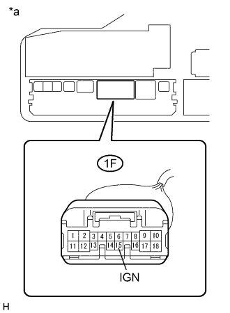
Text in Illustration *a Component without engine room junction block assembly
(Engine Room Relay Block and Junction Block Assembly)
If no signal readings are output, perform troubleshooting according to the following troubleshooting procedure.
-
Remove the engine room junction block assembly Click here.
-
Measure the voltage according to the value(s) in the table below.
Standard Voltage Tester Connection Condition Specified Condition 1F-15 (IGN) - Body ground Engine switch on (IG) 11 to 14 V If the result is not as specified, repair or replace the wire harness or connector.
-
-
-