LANE DEPARTURE ALERT SYSTEM (w/ Dynamic Radar Cruise Control System) Steering Pad Switch Circuit
DESCRIPTION
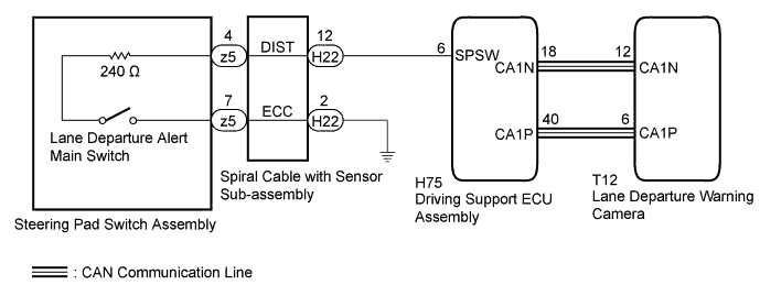
The driving support ECU receives a lane departure alert main switch signal from the steering pad switch assembly and sends the signal to the lane departure warning camera via CAN communication.
WIRING DIAGRAM
INSPECTION PROCEDURE
PROCEDURE
-
READ VALUE USING GTS (CAN BUS CHECK)
-
Connect the GTS to the DLC3.
-
Turn the engine switch on (IG).
-
Enter the following menus: System Select / Can Bus Check.
Result Result Proceed to All of the ECUs and sensors that are currently connected to the CAN communication system are displayed. A None of the ECUs and sensors that are currently connected to the CAN communication system are displayed, or some of them are not displayed. B -
Turn the engine switch off.
B 
GO TO CAN COMMUNICATION SYSTEM Click here
A 
-
-
CHECK FOR DTCs (HEALTH CHECK)
-
Connect the GTS to the DLC3.
-
Turn the engine switch on (IG).
-
Enter the following menus: System Select / Health Check.
-
Check DTCs.
Result Result Proceed to No DTCs are output. A DTCs are output. B -
Turn the engine switch off.
B
GO TO DTC CHART
A
-
-
INSPECT STEERING PAD SWITCH ASSEMBLY
-
Remove the horn button assembly Click here.
-
Disconnect the z5 spiral cable with sensor sub-assembly connector.
-
Measure the resistance according to the value(s) in the table below.
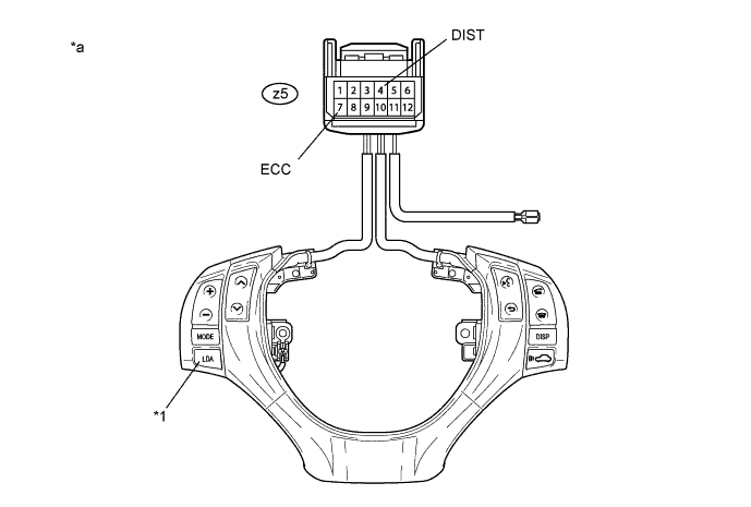
Text in Illustration *1 Lane Departure Alert Main Switch - - *a Component without harness connected
(Steering Pad Switch Assembly)
- - Standard Resistance Tester Connection Condition Specified Condition z5-4 (DIST) - z5-7 (ECC) Lane departure alert main switch being pushed and held 228 to 252 Ω Lane departure alert main switch not pushed 10 kΩ or higher -
Reconnect the z5 spiral cable with sensor sub-assembly connector.
-
Reinstall the horn button assembly Click here.
NG
REPLACE STEERING PAD SWITCH ASSEMBLY Click here
OK
-
-
INSPECT SPIRAL CABLE WITH SENSOR SUB-ASSEMBLY
Note
The spiral cable with sensor sub-assembly is an important part of the SRS airbag system. Incorrect removal or installation of the spiral cable with sensor sub-assembly may cause airbag deployment. Be sure to read the pages shown in the brackets.
-
Remove the spiral cable with sensor sub-assembly.
-
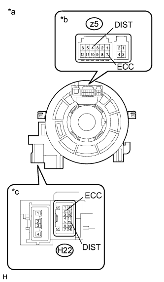
Text in Illustration *a Component without harness connected
(Spiral Cable with Sensor Sub-assembly)
*b Steering Pad Switch Assembly Side *c Vehicle Side Measure the resistance according to the value(s) in the table below.
Standard Resistance Tester Connection Condition Specified Condition z5-4 (DIST) - H22-12 (DIST) The spiral cable with sensor sub-assembly position is center 3 Ω or less The spiral cable with sensor sub-assembly position is 2.5 rotations to the left The spiral cable with sensor sub-assembly position is 2.5 rotations to the right z5-7 (ECC) - H22-2 (ECC) The spiral cable with sensor sub-assembly position is center 3 Ω or less The spiral cable with sensor sub-assembly position is 2.5 rotations to the left The spiral cable with sensor sub-assembly position is 2.5 rotations to the right Tech Tips
The spiral cable with sensor sub-assembly makes a maximum of approximately 5 rotations.
-
After setting the spiral cable with sensor sub-assembly to the center position, rotate the spiral cable with sensor sub-assembly 2.5 times clockwise. Then while rotating the spiral cable with sensor sub-assembly 5 times counterclockwise, measure the resistance according to the value(s) in the table below.
Standard Resistance Tester Connection Condition Specified Condition z5-4 (DIST) - H22-12 (DIST) Always 3 Ω or less z5-7 (ECC) - H22-2 (ECC) Always 3 Ω or less Tech Tips
The spiral cable with sensor sub-assembly makes a maximum of approximately 5 rotations.
-
Reinstall the spiral cable with sensor sub-assembly.
NG
REPLACE SPIRAL CABLE WITH SENSOR SUB-ASSEMBLY Click here
OK
-
-
CHECK HARNESS AND CONNECTOR (SPIRAL CABLE WITH SENSOR SUB-ASSEMBLY - DRIVING SUPPORT ECU ASSEMBLY)
-
Disconnect the H22 spiral cable with sensor sub-assembly connector.
-
Disconnect the H75 driving support ECU assembly connector.
-
Measure the resistance according to the value(s) in the table below.
Standard Resistance (Check for Open) Tester Connection Condition Specified Condition H22-12 (DIST) - H75-6 (SPSW) Always 3 Ω or less Standard Resistance (Check for Short) Tester Connection Condition Specified Condition H22-12 (DIST) or H75-6 (SPSW) - Body ground Always 1 MΩ or higher -
Reconnect the H75 driving support ECU assembly connector.
-
Reconnect the H22 spiral cable with sensor sub-assembly connector.
NG
REPAIR OR REPLACE HARNESS OR CONNECTOR
OK
-
-
CHECK HARNESS AND CONNECTOR (SPIRAL CABLE WITH SENSOR SUB-ASSEMBLY - BODY GROUND)
-
Disconnect the H22 spiral cable with sensor sub-assembly connector.
-
Measure the resistance according to the value(s) in the table below.
Standard Resistance (Check for Open) Tester Connection Condition Specified Condition H22-2 (ECC) - Body ground Always Below 1 Ω -
Reconnect the H22 spiral cable with sensor sub-assembly connector.
NG
REPAIR OR REPLACE HARNESS OR CONNECTOR
OK 
PROCEED TO NEXT SUSPECTED AREA SHOWN IN PROBLEM SYMPTOMS TABLE Click here
-