NAVIGATION SYSTEM (for HDD) AVC-LAN Circuit
DESCRIPTION
Each unit of the navigation system connected to the AVC-LAN (communication bus) transfers switch signals by the audio visual communication local area network.
If a short to +B or short to ground occurs in the AVC-LAN, the navigation system will not function normally as communication is stopped.
INSPECTION PROCEDURE
Note
-
The display and navigation module display is the master unit.
-
When replacing the display and navigation module display, perform vehicle contract setting (w/ G-BOOK system) Click here.
PROCEDURE
-
INSPECT DISPLAY AND NAVIGATION MODULE DISPLAY
-
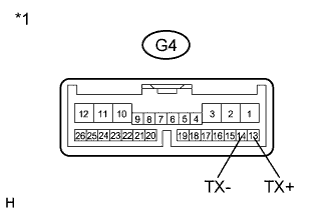
Disconnect the G4 display and navigation module display connector.
-
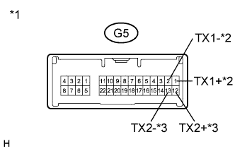
Disconnect the G5 display and navigation module display connector.
-
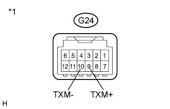
Disconnect the G24 display and navigation module display connector.
-
Measure the resistance according to the value(s) in the table below.
Standard Resistance Tester Connection Condition Specified Condition G4-13 (TX+) - G4-14 (TX-) Always 60 to 80 Ω G5-1 (TX1+) - G5-2 (TX1-) Always 60 to 80 Ω G5-12 (TX2+) - G5-13 (TX2-) Always 60 to 80 Ω G24-9 (TXM+) - G24-10 (TXM-) Always 60 to 80 Ω Text in Illustration *1 Component without harness connected
(Display and Navigation Module Display)
*2 w/ Side Monitor System *3 w/ Headup Display
NG 
REPLACE DISPLAY AND NAVIGATION MODULE DISPLAY Click here
OK 
-
-
CHECK HARNESS AND CONNECTOR (AVC-LAN CIRCUIT)
Tech Tips
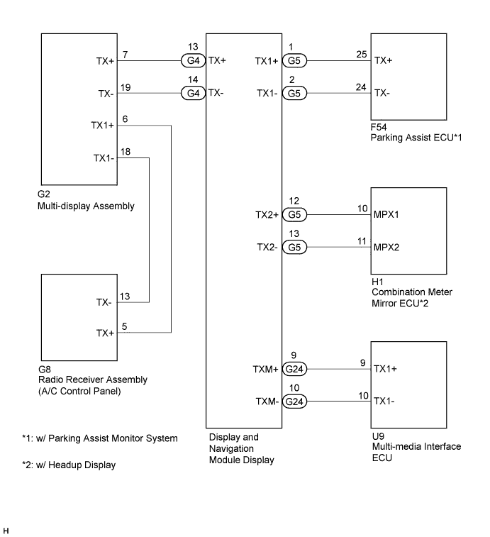
For details of the connectors, refer to Terminals of ECU Click here.
-
Referring to the AVC-LAN wiring diagram below, check all AVC-LAN circuits.
-
Disconnect all connectors in all AVC-LAN circuits.
-
Check for an open or short in all AVC-LAN circuits.
OK There is no open or short circuit.
-
NG
REPAIR OR REPLACE HARNESS OR CONNECTOR
OK
-
-
INSPECT MALFUNCTIONING PARTS
-
Disconnect and reconnect each slave unit one by one until the master unit returns to normal operation.
Tech Tips
-
Check all slave units.
-
If disconnecting a slave unit causes the master unit to return to normal operation, the slave unit is defective and should be replaced.
OK Master unit returns to normal operation. -
NG
REPLACE DISPLAY AND NAVIGATION MODULE DISPLAY Click here
OK 
REPLACE MALFUNCTIONING PARTS
-