ECD SYSTEM (for CCo), Diagnostic DTC:P062D

| DTC Code | DTC Name |
|---|---|
| P062D | Fuel Injector Driver Circuit Performance Bank1 |
DESCRIPTION
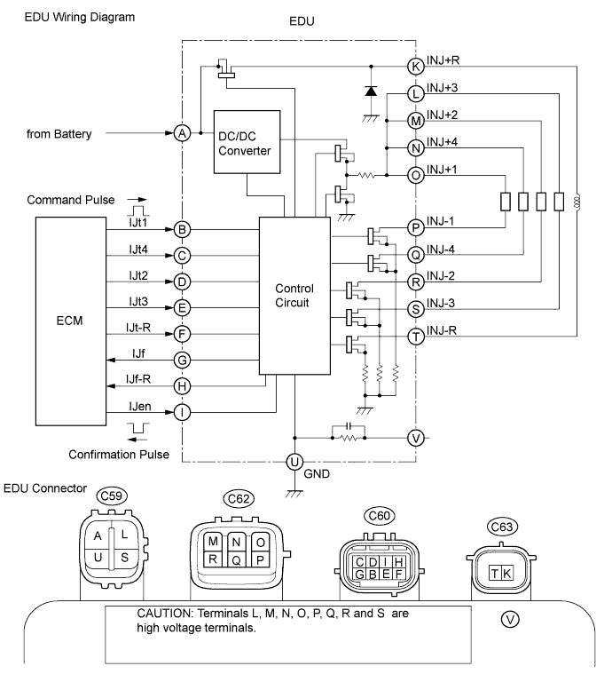
The EDU delivers drive signals to fuel injectors using the DC/DC converter, which provides a high-voltage and quick-charging system.
Soon after the EDU receives a fuel injection command (IJT) signal from the ECM, the EDU responds to the command with an injector injection confirmation (IJF) signal when the current is applied to the fuel injector.
| DTC Detection Drive Pattern | DTC Detection Condition | Trouble Area |
|---|---|---|
| Idling for 5 seconds | Open or short in the injector driver (EDU) or fuel injector circuit. (1 trip detection logic) |
|
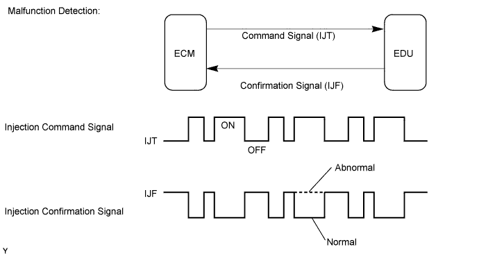
MONITOR DESCRIPTION
P062D (Open or short in EDU or fuel injector circuit):The ECM continuously monitors both injection command (IJT) signals and injection confirmation (IJF) signals. This DTC will be stored if the ECM determines that the number of IJT signals and IJF signals are inconsistent.
The fuel injectors are grounded over a Field Effect Transistor (FET) and a serial resistor. This resistor creates a voltage drop, which is monitored by the EDU (injector drive circuit) in relation to the current drawn by the fuel injector. When the fuel injector current becomes too high, the voltage drop over the resistor exceeds a specified level and no IJF signal for that cylinder is sent to the ECM.
After the engine is started, when there is no injection confirmation (IJF) signal from the EDU to the ECM even though the ECM sends injection command (IJT) signals to the EDU, DTC P062D is stored.
If this DTC is stored, the ECM enters fail-safe mode and limits engine power or stops the engine. The fail-safe mode continues until the ignition switch is turned off.
WIRING DIAGRAM
INSPECTION PROCEDURE
Note
-
After replacing the ECM, the new ECM needs registration Click here and initialization Click here.
-
After replacing a fuel injector, the ECM needs registration Click here.
Tech Tips
Read freeze frame data using the intelligent tester. Freeze frame data records the engine condition when malfunctions are detected. When troubleshooting, freeze frame data can help determine if the vehicle was moving or stationary, if the engine was warmed up or not, and other data from the time the malfunction occurred.
PROCEDURE
-
CHECK ENGINE CRANKING CONDITION
-
Check the engine cranking condition.
Result Result Proceed to Engine does not start A Engine starts, but idling is rough B Except above C Tech Tips
Once DTC P062D is cleared, it is not stored again even when the engine does not start due to a malfunction in the injector driver (EDU).
When the engine cannot be started due to a malfunction in the injector driver (EDU), the value for "Fuel Press" is higher than the value for "Target Common Rail Pressure"
B 
READ VALUE USING INTELLIGENT TESTER (INJECTION FEEDBACK VAL #1 to #4) Click here
C 
CHECK FOR INTERMITTENT PROBLEMS Click here
A 
-
-
INSPECT ECM
-
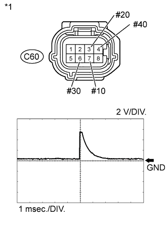
Text in Illustration *1 Front view of wire harness connector
(to Injector Driver (EDU))
Disconnect the injector driver (EDU) connectors.
-
Check the waveform of the injector driver (EDU) connectors using an oscilloscope.
OK Tester Connection Condition Specified Condition C60-7 (#10)- Body ground Cranking Correct waveform is as shown C60-3 (#20) - Body ground Cranking Correct waveform is as shown C60-6 (#30) - Body ground Cranking Correct waveform is as shown C60-4 (#40) - Body ground Cranking Correct waveform is as shown
NG
CHECK HARNESS AND CONNECTOR (EDU - ECM) Click here
OK
-
-
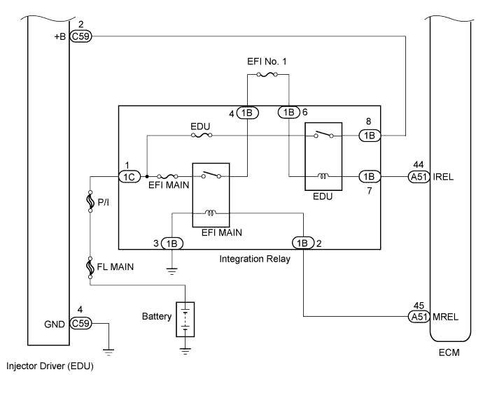
CHECK TERMINAL VOLTAGE EDU POWER SOURCE
-
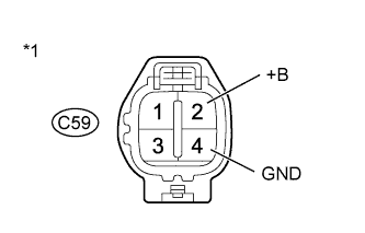
Text in Illustration *1 Front view of wire harness connector
(to Injector Driver (EDU))
Disconnect the injector driver (EDU) connectors.
-
Measure the voltage according to the value(s) in the table below.
Standard Voltage Tester Connection Switch Condition Specified Condition C59-2 (+B) - C59-4 (GND) Ignition switch ON 11 to 14 V -
Reconnect the injector driver (EDU) connectors.
NG
REPAIR OR REPLACE HARNESS OR CONNECTOR Click here
OK
-
-
CHECK HARNESS AND CONNECTOR (EDU - ECM)
-
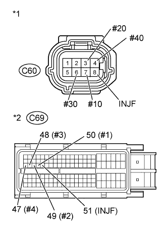
Text in Illustration *1 Front view of wire harness connector
(to Injector Driver (EDU))
*2 Front view of wire harness connector
(to ECM)
Disconnect the EDU connector.
-
Disconnect the ECM connector.
-
Measure the resistance according to the value(s) in the table below.
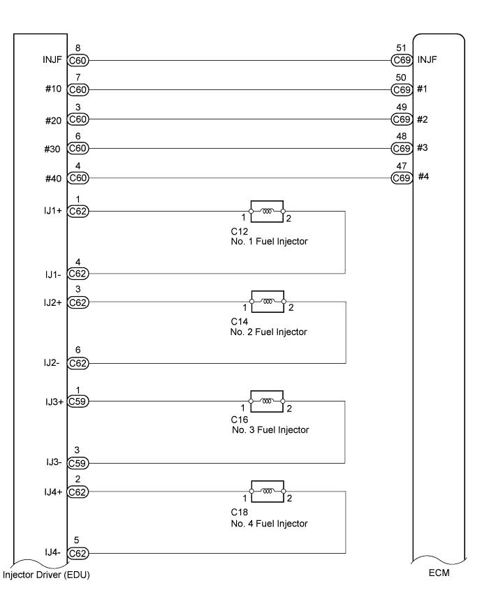
Standard Resistance (Check for Open) Tester Connection Condition Specified Condition C60-7 (#10) - C69-50 (#1) Always Below 1 Ω C60-3 (#20) - C69-49 (#2) Always Below 1 Ω C60-6 (#30) - C69-48 (#3) Always Below 1 Ω C60-4 (#40) - C69-47 (#4) Always Below 1 Ω C60-8 (INJF) - C69-51 (INJF) Always Below 1 Ω Standard Resistance (Check for Short) Tester Connection Condition Specified Condition C60-7 (#10) or C69-50 (#1) - Body ground Always 10 kΩ or higher C60-3 (#20) or C69-49 (#2) - Body ground Always 10 kΩ or higher C60-6 (#30) or C69-48 (#3) - Body ground Always 10 kΩ or higher C60-4 (#40) or C69-47 (#4) - Body ground Always 10 kΩ or higher C60-8 (INJF) or C69-51 (INJF) - Body ground Always 10 kΩ or higher -
Reconnect the EDU connector.
-
Reconnect the ECM connector.
NG
REPAIR OR REPLACE HARNESS OR CONNECTOR Click here
OK
-
-
REPLACE EDU
-
Replace the EDU Click here.
NEXT
CONFIRM WHETHER MALFUNCTION HAS BEEN SUCCESSFULLY REPAIRED Click here
-
-
READ VALUE USING INTELLIGENT TESTER (INJECTION FEEDBACK VAL #1 to #4)
-
Connect the intelligent tester to the DLC3.
-
Turn the ignition switch to ON and turn the tester on.
-
Enter the following menus: Powertrain / Engine and ECT / Data List / Injection Feedback Val #1 to #4.
-
Start the engine.
-
Read the Injection Feedback Val #1 to #4 values while idling the engine.
Standard Value Item Engine Speed* Reference Value Injection Feedback Val #1 to #4 Idling +3.0 mm3/st or less
Tech Tips
-
*: The A/C switch and all accessory switches should be off, and the engine should be fully warmed up.
-
Fuel is not being injected in cylinders whose "Injection Feedback Val" is higher than 3 mm3/st. Inspection procedures beyond this point diagnose whether there are internal problems with fuel injectors, or whether there is a problem in the wiring of the fuel injector system.
-
NEXT
-
-
INSPECT EDU
-
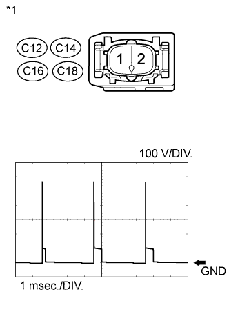
Text in Illustration *1 Front view of wire harness connector
(to Injector)
Disconnect the fuel injector connectors for all cylinders.
Note
If only the injector assembly connector of the malfunctioning cylinder is disconnected, the engine will start and there will be rough idling. Therefore, disconnect all injector assembly connectors before inspecting the waveform.
-
Check the waveform of the fuel injector connectors using an oscilloscope.
OK Tester Connection Condition Specified Condition C12-1 - C12-2 Cranking Voltage increases by 50 V or more C14-1 - C14-2 Cranking Voltage increases by 50 V or more C16-1 - C16-2 Cranking Voltage increases by 50 V or more C18-1 - C18-2 Cranking Voltage increases by 50 V or more
NG
CHECK HARNESS AND CONNECTOR (FUEL INJECTOR - EDU) Click here
OK
-
-
REPLACE FUEL INJECTOR OF MALFUNCTIONING CYLINDER
-
Replace the fuel injector of the malfunctioning cylinder Click here.
NEXT
-
-
BLEED AIR FROM FUEL SYSTEM
-
Bleed the air from the fuel system Click here.
NEXT
-
-
REGISTER INJECTOR COMPENSATION CODE AND PERFORM PILOT QUANTITY LEARNING
-
Register the injector compensation code Click here.
-
Perform the fuel injector pilot quantity learning Click here.
NEXT
CONFIRM WHETHER MALFUNCTION HAS BEEN SUCCESSFULLY REPAIRED Click here
-
-
CHECK HARNESS AND CONNECTOR (EDU - ECM)
-
Text in Illustration *1 Front view of wire harness connector
(to Injector Driver (EDU))
*2 Front view of wire harness connector
(to ECM)
Disconnect the EDU connector.
-
Disconnect the ECM connector.
-
Measure the resistance according to the value(s) in the table below.
Standard Resistance (Check for Open) Tester Connection Condition Specified Condition C60-7 (#10) - C69-50 (#1) Always Below 1 Ω C60-3 (#20) - C69-49 (#2) Always Below 1 Ω C60-6 (#30) - C69-48 (#3) Always Below 1 Ω C60-4 (#40) - C69-47 (#4) Always Below 1 Ω C60-8 (INJF) - C69-51 (INJF) Always Below 1 Ω Standard Resistance (Check for Short) Tester Connection Condition Specified Condition C60-7 (#10) or C69-50 (#1) - Body ground Always 10 kΩ or higher C60-3 (#20) or C69-49 (#2) - Body ground Always 10 kΩ or higher C60-6 (#30) or C69-48 (#3) - Body ground Always 10 kΩ or higher C60-4 (#40) or C69-47 (#4) - Body ground Always 10 kΩ or higher C60-8 (INJF) or C69-51 (INJF) - Body ground Always 10 kΩ or higher -
Reconnect the EDU connector.
-
Reconnect the ECM connector.
NG
REPAIR OR REPLACE HARNESS OR CONNECTOR Click here
OK
-
-
REPLACE ECM
-
Replace the ECM Click here.
NEXT
CONFIRM WHETHER MALFUNCTION HAS BEEN SUCCESSFULLY REPAIRED Click here
-
-
CHECK HARNESS AND CONNECTOR (FUEL INJECTOR - EDU)
-
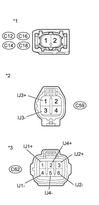
Text in Illustration *1 Front view of wire harness connector
(to Injector)
*2 Front view of wire harness connector
(to Injector Driver (EDU))
*3 Front view of wire harness connector
(to Injector Driver (EDU))
Disconnect the fuel injector connectors.
-
Disconnect the EDU connectors.
-
Measure the resistance according to the value(s) in the table below.
Standard Resistance (Check for Open) Tester Connection Condition Specified Condition C12-1 - C62-1 (IJ1+) Always Below 1 Ω C12-2 - C62-4 (IJ1-) Always Below 1 Ω C14-1 - C62-3 (IJ2+) Always Below 1 Ω C14-2 - C62-6 (IJ2-) Always Below 1 Ω C16-1 - C59-1 (IJ3+) Always Below 1 Ω C16-2 - C59-3 (IJ3-) Always Below 1 Ω C18-1 - C62-2 (IJ4+) Always Below 1 Ω C18-2 - C62-5 (IJ4-) Always Below 1 Ω Standard Resistance (Check for Short) Tester Connection Condition Specified Condition C12-1 or C62-1 (IJ1+) - Body ground Always 10 kΩ or higher C12-2 or C62-4 (IJ1-) - Body ground Always 10 kΩ or higher C14-1 or C62-3 (IJ2+) - Body ground Always 10 kΩ or higher C14-2 or C62-6 (IJ2-) - Body ground Always 10 kΩ or higher C16-1 or C59-1 (IJ3+) - Body ground Always 10 kΩ or higher C16-2 or C59-3 (IJ3-) - Body ground Always 10 kΩ or higher C18-1 or C62-2 (IJ4+) - Body ground Always 10 kΩ or higher C18-2 or C62-5 (IJ4-) - Body ground Always 10 kΩ or higher -
Reconnect the fuel injector connectors.
-
Reconnect the EDU connectors.
NG
REPAIR OR REPLACE HARNESS OR CONNECTOR Click here
OK
-
-
REPLACE EDU
-
Replace the EDU Click here.
NEXT
CONFIRM WHETHER MALFUNCTION HAS BEEN SUCCESSFULLY REPAIRED Click here
-
-
REPAIR OR REPLACE HARNESS OR CONNECTOR
-
Repair or replace the harness or connector.
NEXT
-
-
CONFIRM WHETHER MALFUNCTION HAS BEEN SUCCESSFULLY REPAIRED
-
Connect the intelligent tester to the DLC3.
-
Clear the DTCs Click here.
-
Turn the ignition switch off for 30 seconds or more.
-
Start the engine and idle it for 10 seconds.
-
Enter the following menus: Powertrain / Engine and ECT / DTC.
-
Confirm that the DTC is not output again.
NEXT 
END
-