CYLINDER HEAD GASKET INSTALLATION
PROCEDURE
INSTALL CYLINDER HEAD GASKET
Place a new cylinder head gasket on the cylinder block sub-assembly.
INSTALL CYLINDER HEAD SUB-ASSEMBLY
Note:Place the cylinder head gently in order not to damage the cylinder head gasket.
Place the cylinder head sub-assembly on the cylinder block sub-assembly.
Install the 8 new plate washers to the cylinder head sub-assembly.
Note:Do not drop the plate washers into the cylinder head sub-assembly.
-
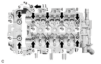
*a
Cylinder Head Bolt (A)
*b
Cylinder Head Bolt (B)
Using the SST, temporarily install and tighten the 11 cylinder head bolts to the specified torque in the order shown in the illustration.
10 N*m
102 kgf*cm
7 ft.*lbf
0109-4
0109-4A
Tighten the 11 cylinder head bolts to the specified torque.
Cylinder Head Bolt (A)
20 N*m
204 kgf*cm
15 ft.*lbf
Cylinder Head Bolt (B)
30 N*m
306 kgf*cm
22 ft.*lbf
-
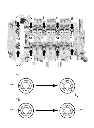
*a
Cylinder Head Bolt (a)
*b
Cylinder Head Bolt (b)
*c
Paint Mark
Mark the front of each cylinder head bolt with paint (for Cylinder Head Bolt (B)).
Tighten the 10 cylinder head bolts by an additional 230°(for Cylinder Head Bolt (a)) or 180°(for Cylinder Head Bolt (b)) as shown in the order shown in the illustration (for Cylinder Head Bolt (B)).
Check that the paint marks are now at a 230°(for Cylinder Head Bolt (a)) or 180°(for Cylinder Head Bolt (b)) angle from the front (for Cylinder Head Bolt (B)).
INSTALL ENGINE MOUNTING INSULATOR SUB-ASSEMBLY RH
Temporarily install the engine mounting insulator sub-assembly RH to the vehicle body with the 3 bolts.
Install the engine mounting insulator sub-assembly RH to the cylinder head sub-assembly with the 3 nuts.
30 N*m
306 kgf*cm
22 ft.*lbf
-
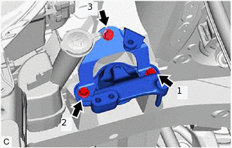
Fully tighten the 3 bolts in the order shown in the illustration.
30 N*m
306 kgf*cm
22 ft.*lbf
Lower the engine, and remove the jack.
INSTALL NO. 1 WATER BY-PASS PIPE
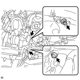
CONNECT ENGINE WIRE
-
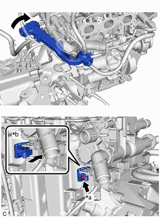
*a
Screw
*b
Lock
Install the engine wire and the slide the lock.
Install the screw.
-
Install the wire harness bracket to the manual transaxle assembly with the 2 nuts.
Connect the engine wire connectors to the cylinder head sub-assembly.
-
INSTALL RADIATOR RESERVE TANK ASSEMBLY
CONNECT HEATER HOSE
INSTALL SPEED SENSOR
CONNECT NO. 1 RADIATOR HOSE
INSTALL EXHAUST MANIFOLD
INSTALL OIL LEVEL GAUGE GUIDE
INSTALL CAMSHAFT
INSTALL NO. 2 CAMSHAFT
ADD ENGINE COOLANT
INSPECT FOR COOLANT LEAK
INSPECT FOR EXHAUST GAS LEAK