POWER STEERING ECU(for Power Tilt and Power Telescopic Steering Column) INSTALLATION
CAUTION / NOTICE / HINT
Tech Tips
-
Use the same procedure for RHD and LHD vehicles.
-
The procedure listed below is for LHD vehicles.
PROCEDURE
-
INSTALL POWER STEERING ECU ASSEMBLY
-
Install a new electric power steering motor shaft damper to the power steering ECU assembly.
-
Install a new electric power steering motor shaft spacer to the power steering ECU assembly.
-
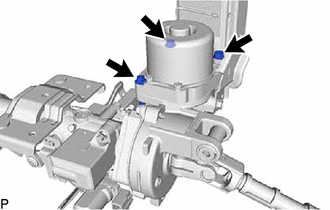
Temporarily install the power steering ECU assembly to the electric power steering column sub-assembly with the 3 bolts.
Note
Do not tighten the bolts until the heads contact the surface of the power steering ECU assembly. Leave a small amount of clearance so that the power steering ECU assembly can be centered in a later procedure.
-
Remove the No. 2 steering intermediate shaft assembly from the electric power steering column sub-assembly.
-
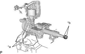
*a Cloth *b Steering Wheel Set Nut or equivalent Secure the electric power steering column sub-assembly in a vise between aluminum plates or pieces of cloth as shown in the illustration.
Note
-
Do not overtighten the vise as the electric power steering column sub-assembly may become deformed.
-
Secure the power steering ECU assembly so that it faces straight up.
-
-
Install the 2 nuts to the electric power steering column sub-assembly.
Tech Tips
The nuts to use are the steering wheel set nut or equivalents.
Steering wheel set nut part No. Thread diameter Thread pitch 09179-12071 12 mm (0.4724 in.) 1.25 mm (0.0492 in.) -
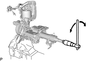
Turn the steering main shaft by 180° to the left and right at a speed of 1 turn per second. Repeat these movements 2 to 3 times to center the power steering ECU assembly.
-
Tighten the 3 bolts.
- Torque:
- 18.5 N*m { 189 kgf*cm, 14 ft.*lbf }
-
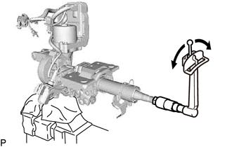
Check the turning torque of the steering main shaft.
Standard preload 0.9 to 1.5 N*m (10 to 15 kgf*cm, 8 to 13 in.*lbf) Note
Make sure that the shaft turns smoothly.
Tech Tips
If the result is not as specified, center the power steering ECU assembly again.
-
Install the No. 2 steering intermediate shaft assembly to the electric power steering column sub-assembly.
- Torque:
- 35.3 N*m { 360 kgf*cm, 26 ft.*lbf }
-
Connect the 2 connector clamps of a new ECU wire harness sub-assembly to the harness bracket.
-
Connect the 3 connectors to the power steering ECU assembly.
-
for LHD:
-
Install the 2 cable ties and heat resistant tape.
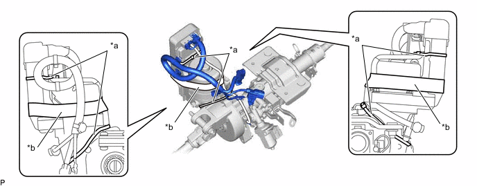
*a Cable Tie *b Heat Resistant Tape Note
As heat from the power steering motor assembly may generate smoke, use heat resistant tape (resistant to 100°C (212°F) or higher).
-
-
Install a new power steering ECU protector to the power steering ECU assembly.
-
-
INSTALL ELECTRIC POWER STEERING COLUMN SUB-ASSEMBLY
-
PERFORM TORQUE SENSOR ZERO POINT CALIBRATION
-
PERFORM ASSIST MAP WRITING