HYBRID BATTERY SYSTEM, Diagnostic DTC:P301A-123
| DTC Code | DTC Name |
|---|---|
| P301A-123 | Open in Hybrid Battery Cell Voltage Detection Circuit |
DESCRIPTION
-
The power management control ECU alerts the driver and performs fail-safe control based on error signals sent from the battery smart unit.
DTC No. INF Code DTC Detection Condition Trouble Area P301A 123 Open in battery block voltage detection circuit
(1 trip detection)
-
HV battery
-
WIRING DIAGRAM
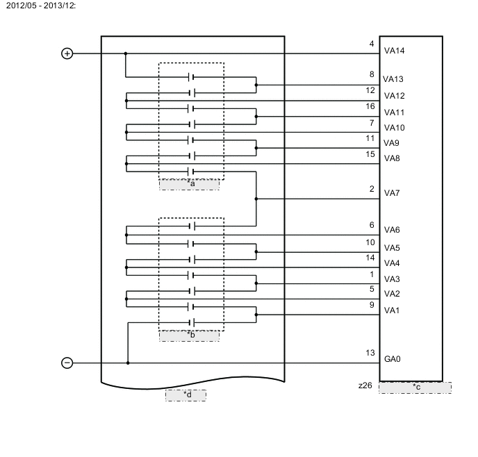
| *a | Battery Block 1 |
| *b | Battery Block 0 |
| *c | Battery Smart Unit |
| *d | HV Battery |

| *a | Battery Block 3 |
| *b | Battery Block 2 |
| *c | Battery Smart Unit |
| *d | HV Battery |

| *a | Battery Block 5 |
| *b | Battery Block 4 |
| *c | Battery Smart Unit |
| *d | HV Battery |

| *a | Battery Block 7 |
| *b | Battery Block 6 |
| *c | Battery Smart Unit |
| *d | HV Battery |
| *a | Battery Block 1 |
| *b | Battery Block 0 |
| *c | Battery Smart Unit |
| *d | HV Battery |

| *a | Battery Block 3 |
| *b | Battery Block 2 |
| *c | Battery Smart Unit |
| *d | HV Battery |
| *a | Battery Block 5 |
| *b | Battery Block 4 |
| *c | Battery Smart Unit |
| *d | HV Battery |

| *a | Battery Block 7 |
| *b | Battery Block 6 |
| *c | Battery Smart Unit |
| *d | HV Battery |
CAUTION / NOTICE / HINT
CAUTION:
-
Before inspecting the high-voltage system or disconnecting the low voltage connector of the inverter with converter assembly, take safety precautions such as wearing insulated gloves and removing the service plug grip to prevent electrical shocks. After removing the service plug grip, put it in your pocket to prevent other technicians from accidentally reconnecting it while you are working on the high-voltage system.
-
After removing the service plug grip, wait for at least 10 minutes before touching any of the high-voltage connectors or terminals. After waiting for 10 minutes, check the voltage at the terminals in the inspection point in the inverter with converter assembly. The voltage should be 0 V before beginning work Click here.
Tech Tips
Waiting for at least 10 minutes is required to discharge the high-voltage capacitor inside the inverter with converter assembly.
-
When disposing of HV battery, make sure to return them through an authorized collection agent who is capable of handling them safely. If they are returned via the manufacturer specified route, they will be returned properly and in a safe manner by an authorized collection agent.
-
Before returning the HV battery, make sure to perform a recovery inspection Click here
-
Make a note of the output DTCs as some of them may be necessary for recovery inspection of the HV battery.
Note
After turning the power switch off, waiting time may be required before disconnecting the cable from the negative (-) auxiliary battery terminal. Therefore, make sure to read the disconnecting the cable from the negative (-) auxiliary battery terminal notices before proceeding with work Click here.
PROCEDURE
-
CHECK DTC OUTPUT (HYBRID CONTROL)
-
Connect the GTS to the DLC3.
-
Turn the power switch on (IG).
-
Enter the following menus: Powertrain / Hybrid Control / Trouble Codes.
-
Read output DTCs.
Result Result Proceed to P301B-123 is not output A P301B-123 is output B -
Turn the power switch off.
B 
GO TO DTC CHART (P301B-123) Click here
A 
-
-
CHECK DTC OUTPUT (HYBRID CONTROL)
-
Connect the GTS to the DLC3.
-
Turn the power switch on (IG).
-
Enter the following menus: Powertrain / Hybrid Control / Trouble Codes.
-
Read output DTCs.
Result Result Proceed to P31AB-123 is not output A P31AB-123 is output B -
Turn the power switch off.
B
GO TO DTC CHART (P31AB-123) Click here
A
-
-
CHECK DTC OUTPUT (HYBRID CONTROL)
-
Connect the GTS to the DLC3.
-
Turn the power switch on (IG).
-
Enter the following menus: Powertrain / Hybrid Control / Trouble Codes.
-
Read output DTCs Click here.
Result Result Proceed to P0AFC-123 is not output. A P0AFC-123 is also output. B -
Turn the power switch off.
B
GO TO DTC CHART (P0AFC-123) Click here
A
-
-
CHECK CONNECTOR CONNECTION CONDITION (BATTERY SMART UNIT CONNECTOR)
CAUTION:
Be sure to wear insulated gloves.
-
Check that the service plug grip is not installed.
Note
After removing the service plug grip, do not turn the power switch on (READY), unless instructed by the repair manual because this may cause a malfunction.
-
Remove the No. 1 hybrid battery shield sub-assembly Click here.
-
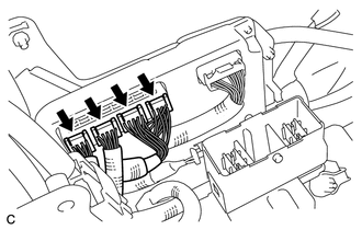
Check the connections of the battery smart unit.
OK The connectors are connected securely and there are no contact problems. -
Install the No. 1 hybrid battery shield sub-assembly.
NG
CONNECT SECURELY
OK
-
-
CLEAR DTC (HYBRID CONTROL)
-
Connect the GTS to the DLC3.
-
Turn the power switch on (IG).
-
Enter the following menus: Powertrain / Hybrid Control / Trouble Codes.
-
Clear the DTCs and freeze frame data.
Note
When DTCs are cleared, freeze frame data and INF codes are also cleared.
-
Turn the power switch off.
NEXT
-
-
RECONFIRM DTC OUTPUT
-
Connect the GTS to the DLC3.
-
Turn the power switch on (IG).
-
Enter the following menus: Powertrain / Hybrid Control / Trouble Codes.
-
Read output DTCs.
Result Result Proceed to P301A-123 is not output A P301A-123 is output B -
Turn the power switch off.
A
RETURNS TO NORMAL OPERATION
B
-
-
CHECK HV BATTERY (BATTERY CELL VOLTAGE)
CAUTION:
Be sure to wear insulated gloves.
-
2012/05 - 2013/12:
-
Check that the service plug grip is not installed.
Note
After removing the service plug grip, do not turn the power switch on (READY), unless instructed by the repair manual because this may cause a malfunction.
-
Remove the No. 1 hybrid battery shield sub-assembly Click here.
-
Disconnect the z26 battery smart unit connector.
-
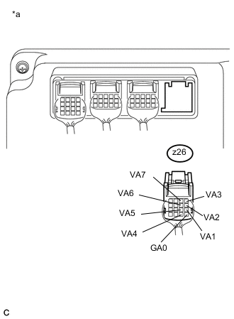
Text in Illustration *a Rear view of wire harness connector
(to Battery Smart Unit)
Measure the voltage according to the value(s) in the table below.
Standard Voltage (Battery Block 0) Tester Connection Switch Condition Specified Condition z26-13 (GA0) - z26-9 (VA1) Power switch off Below 1.9 V z26-9 (VA1) - z26-5 (VA2) Power switch off Below 1.9 V z26-5 (VA2) - z26-1 (VA3) Power switch off Below 1.9 V z26-1 (VA3) - z26-14 (VA4) Power switch off Below 1.9 V z26-14 (VA4) - z26-10 (VA5) Power switch off Below 1.9 V z26-10 (VA5) - z26-6 (VA6) Power switch off Below 1.9 V z26-6 (VA6) - z26-2 (VA7) Power switch off Below 1.9 V Note
Make sure to check the polarity of each terminal (positive (+) or negative (-)) before connecting a tester.
-
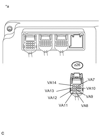
Text in Illustration *a Rear view of wire harness connector
(to Battery Smart Unit)
Measure the voltage according to the value(s) in the table below.
Standard Voltage (Battery Block 1) Tester Connection Switch Condition Specified Condition z26-2 (VA7) - z26-15 (VA8) Power switch off Below 1.9 V z26-15 (VA8) - z26-11 (VA9) Power switch off Below 1.9 V z26-11 (VA9) - z26-7 (VA10) Power switch off Below 1.9 V z26-7 (VA10) - z26-16 (VA11) Power switch off Below 1.9 V z26-16 (VA11) - z26-12 (VA12) Power switch off Below 1.9 V z26-12 (VA12) - z26-8 (VA13) Power switch off Below 1.9 V z26-8 (VA13) - z26-4 (VA14) Power switch off Below 1.9 V Note
Make sure to check the polarity of each terminal (positive (+) or negative (-)) before connecting a tester.
-
Reconnect the z26 battery smart unit connector.
-
Disconnect the z27 battery smart unit connector.
-

Text in Illustration *a Rear view of wire harness connector
(to Battery Smart Unit)
Measure the voltage according to the value(s) in the table below.
Standard Voltage (Battery Block 2) Tester Connection Switch Condition Specified Condition z27-11 (GA1) - z27-6 (VA15) Power switch off Below 1.9 V z27-6 (VA15) - z27-1 (VA16) Power switch off Below 1.9 V z27-1 (VA16) - z27-12 (VA17) Power switch off Below 1.9 V z27-12 (VA17) - z27-7 (VA18) Power switch off Below 1.9 V z27-7 (VA18) - z27-2 (VA19) Power switch off Below 1.9 V z27-2 (VA19) - z27-13 (VA20) Power switch off Below 1.9 V z27-13 (VA20) - z27-8 (VA21) Power switch off Below 1.9 V Note
Make sure to check the polarity of each terminal (positive (+) or negative (-)) before connecting a tester.
-
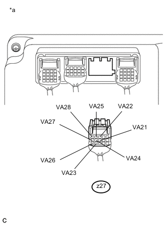
Text in Illustration *a Rear view of wire harness connector
(to Battery Smart Unit)
Measure the voltage according to the value(s) in the table below.
Standard Voltage (Battery Block 3) Tester Connection Switch Condition Specified Condition z27-8 (VA21) - z27-3 (VA22) Power switch off Below 1.9 V z27-3 (VA22) - z27-14 (VA23) Power switch off Below 1.9 V z27-14 (VA23) - z27-9 (VA24) Power switch off Below 1.9 V z27-9 (VA24) - z27-4 (VA25) Power switch off Below 1.9 V z27-4 (VA25) - z27-15 (VA26) Power switch off Below 1.9 V z27-15 (VA26) - z27-10 (VA27) Power switch off Below 1.9 V z27-10 (VA27) - z27-5 (VA28) Power switch off Below 1.9 V Note
Make sure to check the polarity of each terminal (positive (+) or negative (-)) before connecting a tester.
-
Reconnect the z27 battery smart unit connector.
-
Disconnect the z22 battery smart unit connector.
-
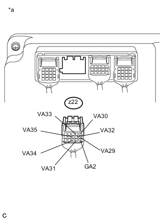
Text in Illustration *a Rear view of wire harness connector
(to Battery Smart Unit)
Measure the voltage according to the value(s) in the table below.
Standard Voltage (Battery block 4) Tester Connection Switch Condition Specified Condition z22-11 (GA2) - z22-6 (VA29) Power switch off Below 1.9 V z22-6 (VA29) - z22-1 (VA30) Power switch off Below 1.9 V z22-1 (VA30) - z22-12 (VA31) Power switch off Below 1.9 V z22-12 (VA31) - z22-7 (VA32) Power switch off Below 1.9 V z22-7 (VA32) - z22-2 (VA33) Power switch off Below 1.9 V z22-2 (VA33) - z22-13 (VA34) Power switch off Below 1.9 V z22-13 (VA34) - z22-8 (VA35) Power switch off Below 1.9 V Note
Make sure to check the polarity of each terminal (positive (+) or negative (-)) before connecting a tester.
-
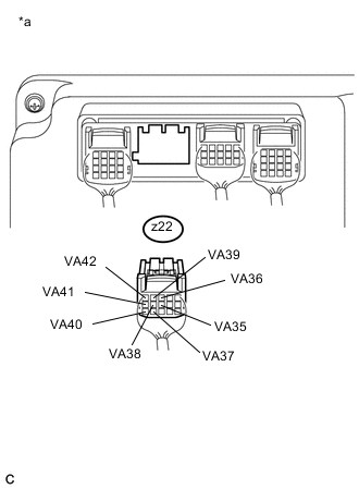
Text in Illustration *a Rear view of wire harness connector
(to Battery Smart Unit)
Measure the voltage according to the value(s) in the table below.
Standard Voltage (Battery block 5) Tester Connection Switch Condition Specified Condition z22-8 (VA35) - z22-3 (VA36) Power switch off Below 1.9 V z22-3 (VA36) - z22-14 (VA37) Power switch off Below 1.9 V z22-14 (VA37) - z22-9 (VA38) Power switch off Below 1.9 V z22-9 (VA38) - z22-4 (VA39) Power switch off Below 1.9 V z22-4 (VA39) - z22-15 (VA40) Power switch off Below 1.9 V z22-15 (VA40) - z22-10 (VA41) Power switch off Below 1.9 V z22-10 (VA41) - z22-5 (VA42) Power switch off Below 1.9 V Note
Make sure to check the polarity of each terminal (positive (+) or negative (-)) before connecting a tester.
-
Reconnect the z22 battery smart unit connector.
-
Disconnect the z23 battery smart unit connector.
-
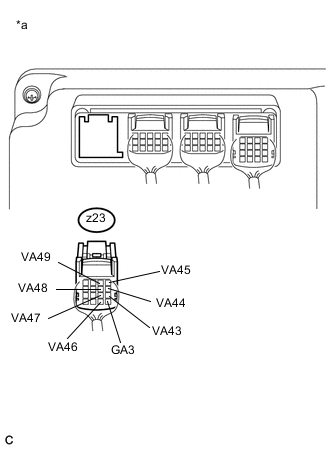
Text in Illustration *a Rear view of wire harness connector
(to Battery Smart Unit)
Measure the voltage according to the value(s) in the table below.
Standard Voltage (Battery Block 6) Tester Connection Switch Condition Specified Condition z23-13 (GA3) - z23-9 (VA43) Power switch off Below 1.9 V z23-9 (VA43) - z23-5 (VA44) Power switch off Below 1.9 V z23-5 (VA44) - z23-1 (VA45) Power switch off Below 1.9 V z23-1 (VA45) - z23-14 (VA46) Power switch off Below 1.9 V z23-14 (VA46) - z23-10 (VA47) Power switch off Below 1.9 V z23-10 (VA47) - z23-6 (VA48) Power switch off Below 1.9 V z23-6 (VA48) - z23-2 (VA49) Power switch off Below 1.9 V Note
Make sure to check the polarity of each terminal (positive (+) or negative (-)) before connecting a tester.
-

Text in Illustration *a Rear view of wire harness connector
(to Battery Smart Unit)
Measure the voltage according to the value(s) in the table below.
Standard Voltage (Battery Block 7) Tester Connection Switch Condition Specified Condition z23-2 (VA49) - z23-15 (VA50) Power switch off Below 1.9 V z23-15 (VA50) - z23-11 (VA51) Power switch off Below 1.9 V z23-11 (VA51) - z23-7 (VA52) Power switch off Below 1.9 V z23-7 (VA52) - z23-16 (VA53) Power switch off Below 1.9 V z23-16 (VA53) - z23-12 (VA54) Power switch off Below 1.9 V z23-12 (VA54) - z23-8 (VA55) Power switch off Below 1.9 V z23-8 (VA55) - z23-4 (VA56) Power switch off Below 1.9 V Note
Make sure to check the polarity of each terminal (positive (+) or negative (-)) before connecting a tester.
Result Result Proceed to Voltage between each pair of terminals is below 1.9 V. B Other than above. A -
Reconnect the z23 battery smart unit connector.
-
Install the No. 1 hybrid battery shield sub-assembly.
-
-
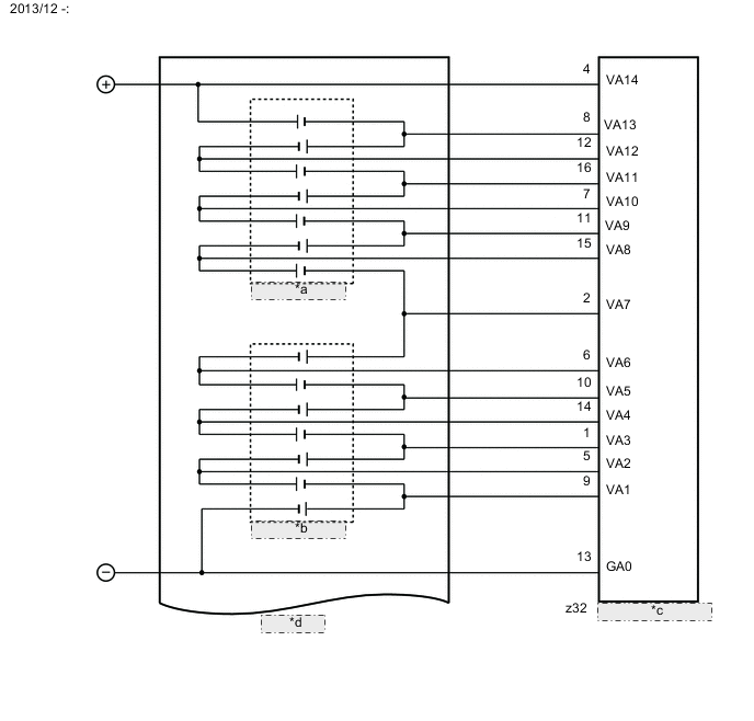
2013/12 -:
-
Check that the service plug grip is not installed.
Note
After removing the service plug grip, do not turn the power switch on (READY), unless instructed by the repair manual because this may cause a malfunction.
-
Remove the No. 1 hybrid battery shield sub-assembly Click here.
-
Disconnect the z32 battery smart unit connector.
-
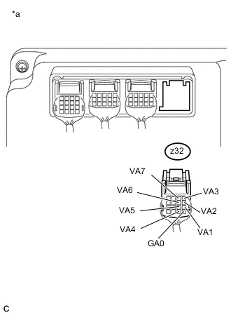
Text in Illustration *a Rear view of wire harness connector
(to Battery Smart Unit)
Measure the voltage according to the value(s) in the table below.
Standard Voltage (Battery Block 0) Tester Connection Switch Condition Specified Condition z32-13 (GA0) - z32-9 (VA1) Power switch off Below 1.9 V z32-9 (VA1) - z32-5 (VA2) Power switch off Below 1.9 V z32-5 (VA2) - z32-1 (VA3) Power switch off Below 1.9 V z32-1 (VA3) - z32-14 (VA4) Power switch off Below 1.9 V z32-14 (VA4) - z32-10 (VA5) Power switch off Below 1.9 V z32-10 (VA5) - z32-6 (VA6) Power switch off Below 1.9 V z32-6 (VA6) - z32-2 (VA7) Power switch off Below 1.9 V Note
Make sure to check the polarity of each terminal (positive (+) or negative (-)) before connecting a tester.
-

Text in Illustration *a Rear view of wire harness connector
(to Battery Smart Unit)
Measure the voltage according to the value(s) in the table below.
Standard Voltage (Battery Block 1) Tester Connection Switch Condition Specified Condition z32-2 (VA7) - z32-15 (VA8) Power switch off Below 1.9 V z32-15 (VA8) - z32-11 (VA9) Power switch off Below 1.9 V z32-11 (VA9) - z32-7 (VA10) Power switch off Below 1.9 V z32-7 (VA10) - z32-16 (VA11) Power switch off Below 1.9 V z32-16 (VA11) - z32-12 (VA12) Power switch off Below 1.9 V z32-12 (VA12) - z32-8 (VA13) Power switch off Below 1.9 V z32-8 (VA13) - z32-4 (VA14) Power switch off Below 1.9 V Note
Make sure to check the polarity of each terminal (positive (+) or negative (-)) before connecting a tester.
-
Reconnect the z32 battery smart unit connector.
-
Disconnect the z33 battery smart unit connector.
-

Text in Illustration *a Rear view of wire harness connector
(to Battery Smart Unit)
Measure the voltage according to the value(s) in the table below.
Standard Voltage (Battery Block 2) Tester Connection Switch Condition Specified Condition z33-11 (GA1) - z33-6 (VA15) Power switch off Below 1.9 V z33-6 (VA15) - z33-1 (VA16) Power switch off Below 1.9 V z33-1 (VA16) - z33-12 (VA17) Power switch off Below 1.9 V z33-12 (VA17) - z33-7 (VA18) Power switch off Below 1.9 V z33-7 (VA18) - z33-2 (VA19) Power switch off Below 1.9 V z33-2 (VA19) - z33-13 (VA20) Power switch off Below 1.9 V z33-13 (VA20) - z33-8 (VA21) Power switch off Below 1.9 V Note
Make sure to check the polarity of each terminal (positive (+) or negative (-)) before connecting a tester.
-
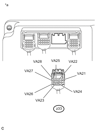
Text in Illustration *a Rear view of wire harness connector
(to Battery Smart Unit)
Measure the voltage according to the value(s) in the table below.
Standard Voltage (Battery Block 3) Tester Connection Switch Condition Specified Condition z33-8 (VA21) - z33-3 (VA22) Power switch off Below 1.9 V z33-3 (VA22) - z33-14 (VA23) Power switch off Below 1.9 V z33-14 (VA23) - z33-9 (VA24) Power switch off Below 1.9 V z33-9 (VA24) - z33-4 (VA25) Power switch off Below 1.9 V z33-4 (VA25) - z33-15 (VA26) Power switch off Below 1.9 V z33-15 (VA26) - z33-10 (VA27) Power switch off Below 1.9 V z33-10 (VA27) - z33-5 (VA28) Power switch off Below 1.9 V Note
Make sure to check the polarity of each terminal (positive (+) or negative (-)) before connecting a tester.
-
Reconnect the z33 battery smart unit connector.
-
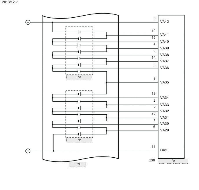
Disconnect the z30 battery smart unit connector.
-

Text in Illustration *a Rear view of wire harness connector
(to Battery Smart Unit)
Measure the voltage according to the value(s) in the table below.
Standard Voltage (Battery block 4) Tester Connection Switch Condition Specified Condition z30-11 (GA2) - z30-6 (VA29) Power switch off Below 1.9 V z30-6 (VA29) - z30-1 (VA30) Power switch off Below 1.9 V z30-1 (VA30) - z30-12 (VA31) Power switch off Below 1.9 V z30-12 (VA31) - z30-7 (VA32) Power switch off Below 1.9 V z30-7 (VA32) - z30-2 (VA33) Power switch off Below 1.9 V z30-2 (VA33) - z30-13 (VA34) Power switch off Below 1.9 V z30-13 (VA34) - z30-8 (VA35) Power switch off Below 1.9 V Note
Make sure to check the polarity of each terminal (positive (+) or negative (-)) before connecting a tester.
-
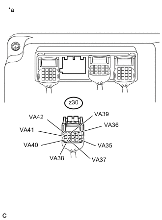
Text in Illustration *a Rear view of wire harness connector
(to Battery Smart Unit)
Measure the voltage according to the value(s) in the table below.
Standard Voltage (Battery block 5) Tester Connection Switch Condition Specified Condition z30-8 (VA35) - z30-3 (VA36) Power switch off Below 1.9 V z30-3 (VA36) - z30-14 (VA37) Power switch off Below 1.9 V z30-14 (VA37) - z30-9 (VA38) Power switch off Below 1.9 V z30-9 (VA38) - z30-4 (VA39) Power switch off Below 1.9 V z30-4 (VA39) - z30-15 (VA40) Power switch off Below 1.9 V z30-15 (VA40) - z30-10 (VA41) Power switch off Below 1.9 V z30-10 (VA41) - z30-5 (VA42) Power switch off Below 1.9 V Note
Make sure to check the polarity of each terminal (positive (+) or negative (-)) before connecting a tester.
-
Reconnect the z30 battery smart unit connector.
-
Disconnect the z31 battery smart unit connector.
-
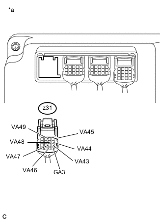
Text in Illustration *a Rear view of wire harness connector
(to Battery Smart Unit)
Measure the voltage according to the value(s) in the table below.
Standard Voltage (Battery Block 6) Tester Connection Switch Condition Specified Condition z31-13 (GA3) - z31-9 (VA43) Power switch off Below 1.9 V z31-9 (VA43) - z31-5 (VA44) Power switch off Below 1.9 V z31-5 (VA44) - z31-1 (VA45) Power switch off Below 1.9 V z31-1 (VA45) - z31-14 (VA46) Power switch off Below 1.9 V z31-14 (VA46) - z31-10 (VA47) Power switch off Below 1.9 V z31-10 (VA47) - z31-6 (VA48) Power switch off Below 1.9 V z31-6 (VA48) - z31-2 (VA49) Power switch off Below 1.9 V Note
Make sure to check the polarity of each terminal (positive (+) or negative (-)) before connecting a tester.
-
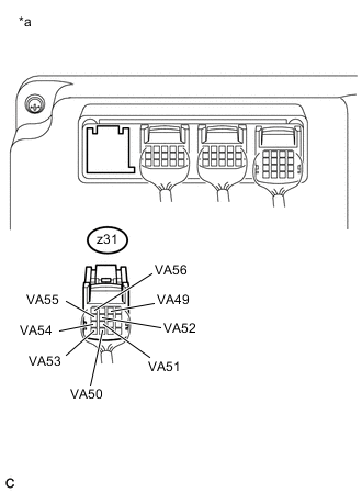
Text in Illustration *a Rear view of wire harness connector
(to Battery Smart Unit)
Measure the voltage according to the value(s) in the table below.
Standard Voltage (Battery Block 7) Tester Connection Switch Condition Specified Condition z31-2 (VA49) - z31-15 (VA50) Power switch off Below 1.9 V z31-15 (VA50) - z31-11 (VA51) Power switch off Below 1.9 V z31-11 (VA51) - z31-7 (VA52) Power switch off Below 1.9 V z31-7 (VA52) - z31-16 (VA53) Power switch off Below 1.9 V z31-16 (VA53) - z31-12 (VA54) Power switch off Below 1.9 V z31-12 (VA54) - z31-8 (VA55) Power switch off Below 1.9 V z31-8 (VA55) - z31-4 (VA56) Power switch off Below 1.9 V Note
Make sure to check the polarity of each terminal (positive (+) or negative (-)) before connecting a tester.
Result Result Proceed to Voltage between each pair of terminals is below 1.9 V. B Other than above. A -
Reconnect the z31 battery smart unit connector.
-
Install the No. 1 hybrid battery shield sub-assembly.
-
A
REPLACE BATTERY SMART UNIT Click here
B
REPLACE HV BATTERY Click here
-