STEERING COLUMN ASSEMBLY INSPECTION
CAUTION / NOTICE / HINT
Note
When using a vise, do not overtighten it.
PROCEDURE
-
INSPECT PRELOAD
-
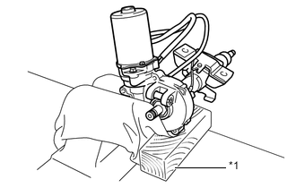
Text in Illustration *1 Wooden Block Secure the steering column assembly in a vice using aluminum plates and wooden block as shown in the illustration.
Note
-
Do not overtighten the vice, as the steering column assembly may become deformed.
-
Support the steering column assembly with a wooden block or similar item to ensure that it does not fall.
-
-
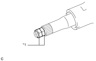
Text in Illustration *1 Service Nut Install the 2 service nuts to the steering main shaft.
Recommended service nut Thread diameter 12.0 mm (0.472 in.) Thread pitch 1.25 mm (0.0492 in.) -
Tighten the 2 service nuts each other to lock them.
Note
Do not apply excess torque to the service nuts by using a tool such as an impact wrench.
Tech Tips
These nuts are installed to turn the steering main shaft. They should be removed after inspecting the steering main shaft rotating torque.
-
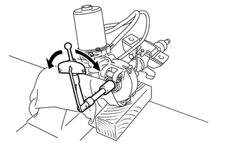
Using a torque wrench, turn the main shaft and measure the preload.
Preload 1.6 to 2.1 N*m (16.3 to 21.4 kgf*cm, 14.2 to 18.6 in.*lbf) If the preload is not as specified, replace the steering column assembly with a new one.
-
-
INSPECT STEERING LOCK OPERATION (w/o Entry and Start System)
-
Check that the steering lock mechanism is activated when the key is removed.
-
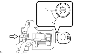
Text in Illustration *a LOCK *b ACC Check that the steering lock mechanism is deactivated when the key is inserted and turned to the ACC position.
Tech Tips
If there is any abnormality, replace the ignition switch lock cylinder assembly or steering column upper bracket assembly.
-
-
INSPECT STEERING COLUMN ASSEMBLY
-
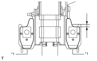
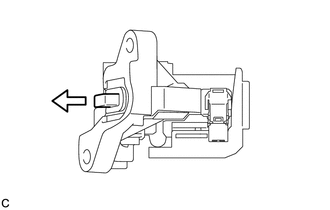
Text in Illustration *1 Capsule Check that the 2 capsules are securely installed to the steering column assembly as shown in the illustration.
OK 5.0 mm (0.1969 in.) or more If the capsules are not positioned as specified, replace the steering column assembly with a new one.
-
Check the 2 capsules for deformation and damage.
If either of the capsules is deformed, loose, missing or damaged, replace the steering column assembly with a new one.
-
-
INSPECT STEERING INTERMEDIATE SHAFT ASSEMBLY
-
Check for play
-
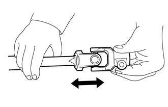
Check that there is no play at the universal joint.
OK No play Tech Tips
If the result is not as specified, replace the steering intermediate shaft assembly with a new one.
-
-
Turning toque
-
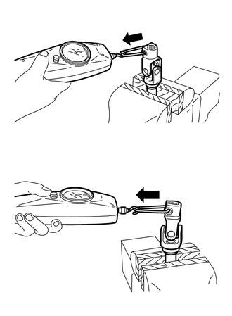
Hold the steering intermediate shaft assembly in a vise with the yoke on the rack and pinion power steering gear assembly side facing upward.
-
Using a push and pull gauge, measure the turning torque in the both directions.
Torque 6.6 N*m (66 kgf*cm, 58 in.*lbf) or less Tech Tips
If the result is not as specified, replace the steering intermediate shaft assembly with a new one.
-
Hold the steering intermediate shaft assembly in a vise with the yoke on the steering column assembly side facing upward.
-
Using a push and pull gauge, measure the turning torque in the both directions.
Torque 6.0 N*m (61 kgf*cm, 53 in.*lbf) or less Tech Tips
If the result is not as specified, replace the steering intermediate shaft assembly with a new one.
-
-