EASY ACCESS BUCKLE SYSTEM TERMINALS OF ECU
-
POSITION CONTROL ECU ASSEMBLY

-
Disconnect the Q7 and Q8 position control ECU assembly connector.
-
Measure the voltage and resistance according to the value(s) in the table below.
Terminal No. (Symbol) Wiring Color Terminal Description Condition Specified Condition Q7-1 (+B2) - Body ground W - Body ground Battery power supply Always 11 to 14 V Q8-1 (GND2) - Body ground W-B - Body ground Ground Always Below 1 Ω Q8-2 (GND1) - Body ground W-B - Body ground Ground Always Below 1 Ω Q8-19 (IG) - Body ground SB - Body ground IG power supply Engine switch on (IG) 11 to 14 V Engine switch off Below 1 V -
Reconnect the Q7 and Q8 position control ECU assembly connector.
-
Measure the voltage and resistance according to the value(s) in the table below.
Terminal No. (Symbol) Wiring Color Terminal Description Condition Specified Condition Q6-4 (BCL-) - Body ground B - Body ground Driver side buckle motor DOWN output Easy access buckle function OFF Below 1 V B - Body ground Easy access buckle function ON (descended) 11 to 14 V Q6-10 (BCL+) - Body ground R - Body ground Driver side buckle motor UP output Easy access buckle function OFF Below 1 V Easy access buckle function ON (raised) 11 to 14 V Q7-23 (BCLL) - Body ground BR - Body ground Driver side buckle switch LED light output Buckle switch LED light illuminated → not illuminated 11 to 14 V → Below 1 V Q8-12 (SSLB) - Body ground SB - Body ground Driver side buckle sensor output Buckle motor operating 4.7 to 5.1 V Q8-16 (SGND) - Body ground GR - Body ground Ground Always Below 1 Ω Q8-20 (DBCL) - Body ground BR - Body ground Driver side tongue plate fastening condition Driver side seat belt is fastened Below 1 V Driver side seat belt is unfastened 11 to 14 V
-
-
NO. 2 POSITION CONTROL ECU ASSEMBLY
-
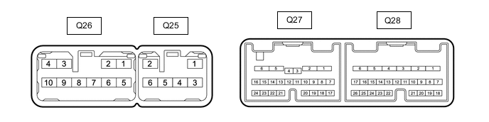
Disconnect the Q27 and Q28 No. 2 position control ECU assembly connector.
-
Measure the voltage and resistance according to the value(s) in the table below.
Terminal No. (Symbol) Wiring Color Terminal Description Condition Specified Condition Q27-1 (+B2) - Body ground W - Body ground Battery power supply Always 11 to 14 V Q28-1 (GND2) - Body ground W-B - Body ground Ground Always Below 1 Ω Q28-2 (GND1) - Body ground W-B - Body ground Ground Always Below 1 Ω -
Reconnect the Q27 and Q28 No. 2 position control ECU assembly connector.
-
Measure the voltage and resistance according to the value(s) in the table below.
Terminal No. (Symbol) Wiring Color Terminal Description Condition Specified Condition Q26-4 (BCL-) - Body ground B - Body ground Front passenger side buckle motor DOWN output Easy access buckle function OFF Below 1 V B - Body ground Easy access buckle function ON (descended) 11 to 14 V Q26-10 (BCL+) - Body ground R - Body ground Front passenger side buckle motor UP output Easy access buckle function OFF Below 1 V Easy access buckle function ON (raised) 11 to 14 V Q27-23 (BCLL) - Body ground BR - Body ground Front passenger side buckle switch LED light output Buckle switch LED light illuminated → not illuminated 11 to 14 V → Below 1 V Q28-12 (SSLB) - Body ground SB - Body ground Front passenger side buckle sensor output Buckle motor operating 4.7 to 5.1 V Q28-16 (SGND) - Body ground GR - Body ground Ground Always Below 1 Ω Q28-20 (DBCL) - Body ground BR - Body ground Front passenger side tongue plate fastening condition Driver side seat belt is fastened Below 1 V Driver side seat belt is unfastened 11 to 14 V
-
-
CHECK INSTRUMENT PANEL JUNCTION BLOCK ASSEMBLY AND MAIN BODY ECU (MULTIPLEX NETWORK BODY ECU)
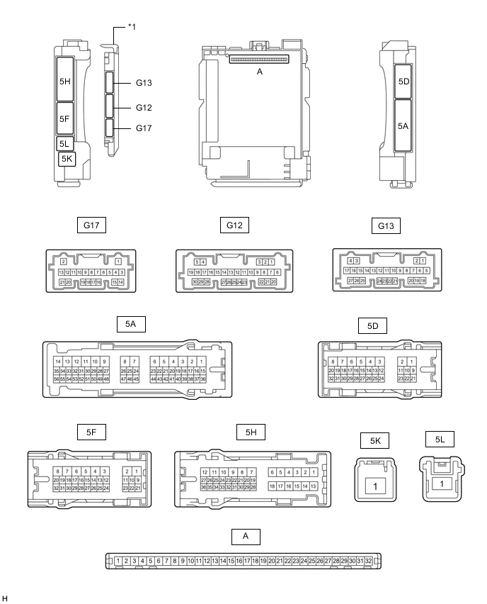
*1 Main Body ECU (Multiplex Network Body ECU) - -
-
Remove the main body ECU (multiplex network body ECU) from the instrument panel junction block assembly.
-
Reconnect the instrument panel junction block assembly connectors.
-
Measure the voltage and resistance according to the value(s) in the table below.
Tester Connection Wiring Color Input/Output Terminal Description Condition Specified Condition Related Data List Item A-11 (GND1) - Body ground - - Ground Always Below 1 Ω - A-30 (ACC) - Body ground - Input ACC power supply Engine switch on (ACC) 11 to 14 V ACC SW Engine switch off Below 1 V A-31 (BECU) - Body ground - Input Battery power supply Always 11 to 14 V - A-32 (IG) - Body ground - Input IG power supply Engine switch on (IG) 11 to 14 V IG SW Engine switch off Below 1 V -
Install the main body ECU (multiplex network body ECU) to the instrument panel junction block assembly
-
Measure the voltage and pulse according to the value(s) in the table below.
Terminal No. (Symbol) Wiring Color Terminal Description Condition Specified Condition G12-2 (FLCL) - Body ground V - Body ground Courtesy light assembly (for Front LH Side) output Courtesy light assembly (for front LH side) on Below 1 V Courtesy light assembly (for front LH side) off 11 to 14 V G12-3 (FRCL) - Body ground G - Body ground Courtesy light assembly (for Front RH Side) output Courtesy light assembly (for front RH side) on 11 to 14 V Courtesy light assembly (for front RH side) off Below 1 V
-