FRONT SIDE MEMBER CUT AND JOIN REPLACEMENT SECTIONS (SMALL AREAS)
With the front side member extension assembly removed.
REMOVAL
Symbol Meaning

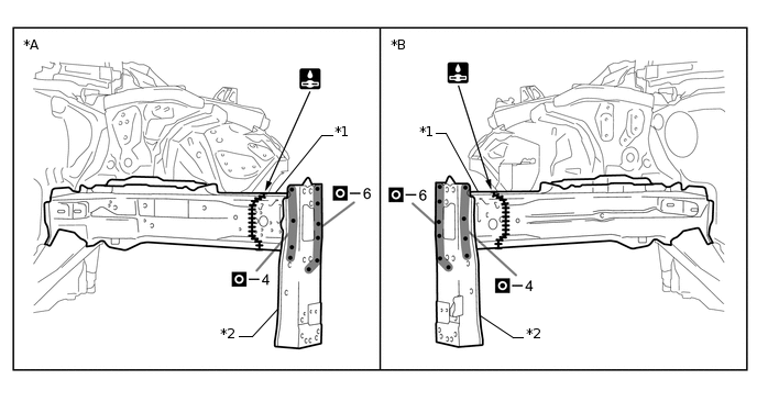
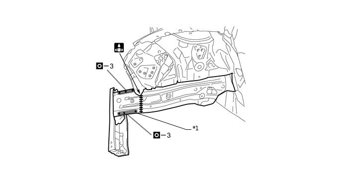
Remove Weld Points

Cut and Join Location
Carefully cut the front side member inner so as not to damage A.
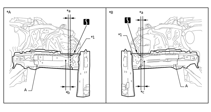
*A
LH
*B
RH
*1
FRONT SIDE MEMBER INNER
-
-
*a
5 mm (0.20 in.)
*b
35 mm (1.38 in.)
*c
20 mm (0.79 in.)
-
-
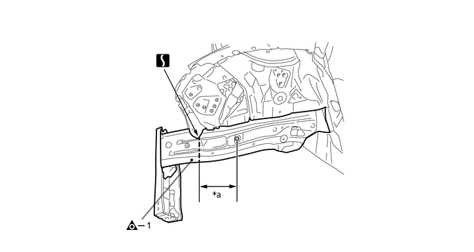
*a
180 mm (7.09 in.)
-
-
INSTALLATION
Symbol Meaning

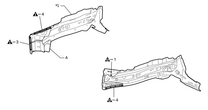
Plug Weld

Butt Weld
Remove A from the new parts.
*1
FRONT SIDE MEMBER SUB-ASSEMBLY OUTER
-
-
Temporarily install the new parts and measure each part of the new parts in accordance with the body dimension diagram. (See the body dimensions)
*A
LH
*B
RH
*1
FRONT SIDE MEMBER INNER
*2
FRONT BUMPER MOUNTING REINFORCE SUB-ASSEMBLY
*1
FRONT SIDE MEMBER PLATE OUTER
-
-
After applying the top coat, apply anti-rust agent to the internal panel portion of the closed section structural weld points.