SFI SYSTEM, Diagnostic DTC:P0420
| DTC Code | DTC Name |
|---|---|
| P0420 | Catalyst System Efficiency Below Threshold (Bank 1) |
DESCRIPTION
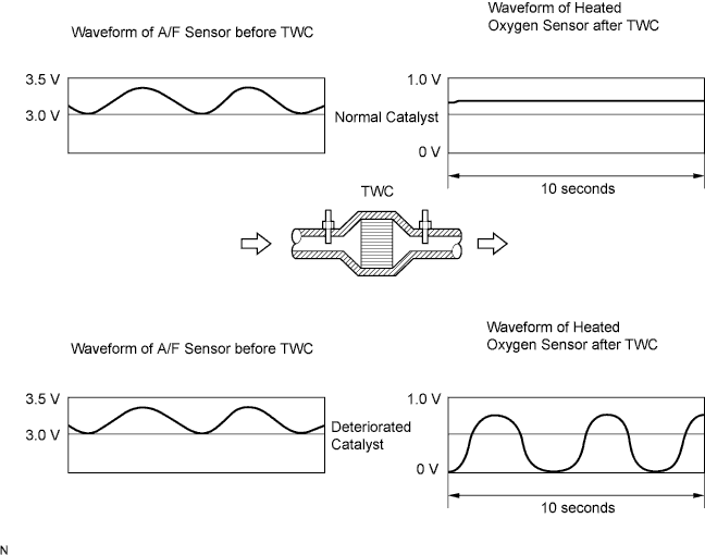
The ECM uses 2 sensors located in front of and behind the Three-Way Catalytic Converter (TWC) to monitor its efficiency. The Air-fuel Ratio (A/F) sensor (sensor 1) sends pre-catalyst information to the ECM. The Heated Oxygen (HO2) sensor (sensor 2) sends post-catalyst information to the ECM. The ECM compares these two signals to judge the efficiency of the catalyst and the catalyst's ability to store oxygen. During normal operation the TWC stores and releases oxygen as needed. The capacity to store oxygen results in a low variation in the post-TWC exhaust stream as shown below.
If the catalyst is functioning normally, the waveform of the HO2 sensor slowly changes between rich and lean. If the catalyst is deteriorated, the waveform will fluctuate frequently between rich and lean. As the catalyst efficiency degrades, its ability to store oxygen is reduced and the catalyst output becomes more variable.
When running the monitor, the ECM compares sensor signals before and after the TWC over a specific amount of time to determine catalyst efficiency. The ECM begins the comparison by calculating the signal length for both sensors (using each output voltage of the sensors). If the HO2 sensor signal length is greater than the threshold (the threshold is calculated based on the A/F sensor signal length), the ECM concludes that the TWC is malfunctioning.
The ECM will turn on the MIL and the DTC will be set.
| DTC No. | DTC Detection Condition | Trouble Area |
|---|---|---|
| P0420 | After engine and catalyst are warmed up, and while vehicle is driven within set vehicle speed and engine speed range: Waveform of heated oxygen sensor frequently fluctuates between rich and lean (2 trip detection logic) |
|
CONFIRMATION DRIVING PATTERN
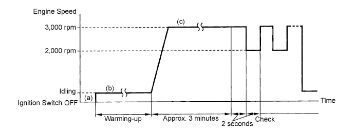
(a) Start the engine and warm it up with all the accessories turned OFF until the engine coolant temperature becomes stable.
(b) Run the engine at 2,500 to 3,000 rpm for approximately 3 minutes.
(c) Rev the engine to 3,000 rpm for 2 seconds and 2,000 rpm for 2 seconds alternately.
A/F CONTROLTech Tips
Malfunctioning areas can be identified by performing the "Control the Injection Volume" function provided in the Active Test. The "Control the Injection Volume" function can help to determine whether the Air-fuel Ratio (A/F) sensor, heated oxygen (HO2) sensor and other potential trouble areas are malfunctioning.
The following instructions describe how to conduct the "Control the Injection Volume" operation using intelligent tester.
-
Connect the intelligent tester to the DLC3.
-
Start the engine and turn the tester ON.
-
Warm up the engine at an engine speed of 2,500 rpm for approximately 90 seconds.
-
On the tester, select the following menu items: Powertrain / Engine and ECT / Active Test / Control the Injection Volume.
-
Perform the "Control the Injection Volume" operation with the engine in an idling condition (press the RIGHT or LEFT button to change the fuel injection volume).
-
Monitor the output voltage of the A/F and HO2 sensors (AFS B1 S1 and O2S B1 S2) displayed on the tester.
Tech Tips
-
The "Control the Injection Volume" operation lowers the fuel injection volume by 12.5% or increases the injection volume by 24.8%.
-
Each sensor reacts in accordance with increases in the fuel injection volume.
| Standard | ||||||||||||||||||||
|---|---|---|---|---|---|---|---|---|---|---|---|---|---|---|---|---|---|---|---|---|
|
Note
The Air-fuel Ratio (A/F) sensor has an output delay of a few seconds and the Heated Oxygen (HO2) sensor has a maximum output delay of approximately 20 seconds.
| Case | A/F Sensor (Sensor 1) Output Voltage |
HO2 Sensor (Sensor 2) Output Voltage |
Main Suspected Trouble Area | ||
|---|---|---|---|---|---|
| 1 | Injection Volume +24.8% -12.5% |
 |
Injection Volume +24.8% -12.5% |
|
- |
| Output Voltage More than 3.35 V Less than 3.0 V |
 |
Output Voltage More than 0.55 V Less than 0.4 V |
 |
||
| 2 | Injection Volume +24.8% -12.5% |
|
Injection Volume +24.8% -12.5% |
|
|
| Output Voltage Almost no reaction |
 |
Output Voltage More than 0.55 V Less than 0.4 V |
|
||
| 3 | Injection Volume +24.8% -12.5% |
|
Injection Volume +24.8% -12.5% |
|
|
| Output Voltage More than 3.35 V Less than 3.0 V |
|
Output Voltage Almost no reaction |
|
||
| 4 | Injection volume +24.8% -12.5% |
|
Injection Volume +24.8% -12.5% |
|
|
| Output Voltage Almost no reaction |
|
Output Voltage Almost no reaction |
|
||
-
The following "Control the Injection Volume" procedure enables the technicians to check and graph the output voltages of both A/F sensor and heated oxygen sensor.
-
To display the graph, select the following menu items on the tester: View / Line graph.
INSPECTION PROCEDURE
Tech Tips
Read freeze frame data using the intelligent tester. Freeze frame data records the engine conditions when malfunctions are detected. When troubleshooting, freeze frame data can help determine if the vehicle was moving or stationary, if the engine was warmed up or not, if the air-fuel ratio was lean or rich, and other data from the time the malfunction occurred.
PROCEDURE
-
CHECK OTHER DTCS OUTPUT (IN ADDITION TO DTC P0420)
-
Connect the intelligent tester to the DLC3.
-
Turn the ignition switch ON and turn the intelligent tester ON.
-
Select the following menu items: Powertrain / Engine and ECT / DTC.
-
Read DTCs.
Result Display (DTC output) Proceed to P0420 A P0420 and other DTCs B Tech Tips
If any other DTCs besides P0420 are output, perform troubleshooting for those DTCs first.
B 
GO TO RELEVANT DTC CHART
A 
-
-
PERFORM ACTIVE TEST (CONTROL THE INJECTION VOLUME)
-
Connect the intelligent tester to the DLC3.
-
Start the engine and turn the tester ON.
-
Warm up the engine at an engine speed of 2,500 rpm for approximately 90 seconds.
-
On the tester, select the following menu items: Powertrain / Engine and ECT / Active Test / Control the Injection Volume.
-
Perform the Control the Injection Volume operation with the engine in an idling condition (press the right or left button to change the fuel injection volume.)
-
Monitor the output voltages of the A/F and HO2 sensors (AFS B1 S1 and O2S B1 S2 or AFS B2S1 and O2S B2S2) displayed on the tester.
Tech Tips
-
The "Control the Injection Volume" operation lowers the fuel injection volume by 12.5% or increases the injection volume by 24.8%.
-
Each sensor reacts in accordance with increases and decreases in the fuel injection volume.
Standard Tester Display
(Sensor)
Injection Volume Status Voltage AFS B1 S1
(A/F)
+24.8% Rich Less than 3.0 V AFS B1 S1
(A/F)
-12.5% Lean More than 3.35 V O2S B1 S2
(HO2)
+24.8% Rich More than 0.55 V O2S B1 S2
(HO2)
-12.5% Lean Less than 0.4 V Result: Status
AFS B1 S1
Status
O2S B1 S2
A/F Condition and A/F and
HO2 Sensor Condition
Misfire Main Suspected Trouble Areas Proceed to Lean/Rich Lean/Rich Normal -
-
Three-Way Catalytic Converter (TWC)
-
Gas leakage from exhaust system
A Lean Lean/Rich A/F sensor malfunction -
-
A/F sensor
B Rich Lean/Rich A/F sensor malfunction -
-
A/F sensor
B Lean/Rich Lean HO2 sensor malfunction -
-
HO2 sensor
-
Gas leakage from exhaust system
C Lean/Rich Rich HO2 sensor malfunction -
-
HO2 sensor
-
Gas leakage from exhaust system
C Lean Lean Actual air-fuel ratio lean May occur
-
Extremely rich or lean actual air-fuel ratio
-
Gas leakage from exhaust system
A Rich Rich Actual air-fuel ratio lean -
-
Extremely rich or lean actual air-fuel ratio
-
Gas leakage from exhaust system
A Lean: During the Control the Injection Volume Active Test, the A/F sensor output voltage (AFS) is consistently more than 3.35 V, and the HO2 sensor output voltage (O2S) is consistently less than 0.4 V.
Rich: During the Control the Injection Volume Active Test, the AFS is consistently less than 3.0 V, and the O2S is consistently more than 0.55 V.
-
B
CHECK AND REPLACE AIR FUEL RATIO SENSOR
C
CHECK AND REPLACE HEATED OXYGEN SENSOR, AND CHECK AND REPAIR EXHAUST GAS LEAKAGE
A
-
-
CHECK FOR EXHAUST GAS LEAKAGE
OK No gas leakage.
NG
REPAIR OR REPLACE EXHAUST GAS LEAKAGE POINT
OK 
REPLACE THREE-WAY CATALYTIC CONVERTER