AIR CONDITIONING SYSTEM(for Automatic Air Conditioning System), Diagnostic DTC:B14A2
| DTC Code | DTC Name |
|---|---|
| B14A2 | Driver Side Solar Sensor Short Circuit |
DESCRIPTION
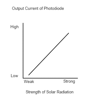
The cooler thermistor (solar sensor), which is installed on the upper side of the instrument panel, detects sunlight and controls the air conditioning in auto mode. The output current from the solar sensor varies according to the amount of sunlight. When the amount of sunlight increases, the output current increases. As the amount of sunlight decreases, the output current decreases. The air conditioning amplifier assembly detects the output current from the solar sensor.
DTC Code |
DTC Detection Condition |
Trouble Area |
|---|---|---|
B14A2 |
An open or short in the driver side solar sensor circuit. |
|
If the check is performed in a dark place, DTC B14A2 or B14A3 (solar sensor circuit abnormal) may be stored even though the system is normal.
WIRING DIAGRAM
PROCEDURE
READ VALUE USING INTELLIGENT TESTER
Use the Data List to check if the solar sensor is functioning properly.
Table 1. Air Conditioner Tester Display
Measurement Item/Range
Normal Condition
Diagnostic Note
Solar Sensor (D Side)
Solar sensor / Min.: 0, Max.: 255
Driver side solar sensor voltage increases as brightness increases
Open in the circuit: 0.
Short in the circuit: 255.
OK
The display is as specified in the normal condition column.
Table 2. Result Result
Proceed to
OK (When troubleshooting according to Problem Symptoms Table)
A
OK (When troubleshooting according to the DTC)
B
NG
C
CHECK HARNESS AND CONNECTOR (SOLAR SENSOR - AIR CONDITIONING AMPLIFIER)
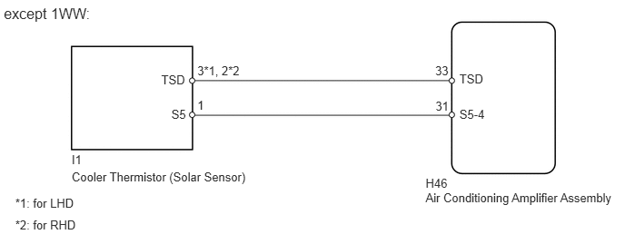
except 1WW:
Disconnect the I1 sensor connector.
Disconnect the H46 amplifier connector.
Measure the resistance according to the value(s) in the table below.
Standard Resistance
Table 3. for LHD Tester Connection
Condition
Specified Condition
H46-33 (TSD) - I1-3 (TSD)
Always
Below 1 Ω
H46-31 (S5-4) - I1-1 (S5)
Always
Below 1 Ω
H46-33 (TSD) - Body ground
Always
10 kΩ or higher
H46-31 (S5-4) - Body ground
Always
10 kΩ or higher
Table 4. for RHD Tester Connection
Condition
Specified Condition
H46-33 (TSD) - I1-2 (TSD)
Always
Below 1 Ω
H46-31 (S5-4) - I1-1 (S5)
Always
Below 1 Ω
H46-33 (TSD) - Body ground
Always
10 kΩ or higher
H46-31 (S5-4) - Body ground
Always
10 kΩ or higher
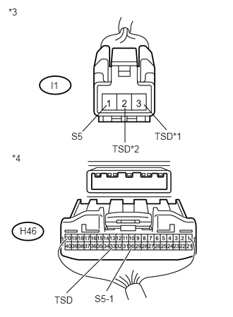
Table 5. Text in Illustration *1
for LHD
*2
for RHD
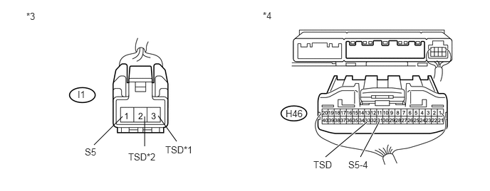
*3
Front view of wire harness connector
(to Solar Sensor)
*4
Rear view of wire harness connector
(to Air Conditioning Amplifier Assembly)
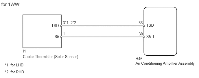
for 1WW:
-
Disconnect the I1 sensor connector.
Disconnect the H46 amplifier connector.
Measure the resistance according to the value(s) in the table below.
Standard Resistance
Table 6. for LHD Tester Connection
Condition
Specified Condition
H46-33 (TSD) - I1-3 (TSD)
Always
Below 1 Ω
H46-30 (S5-1) - I1-1 (S5)
Always
Below 1 Ω
H46-33 (TSD) - Body ground
Always
10 kΩ or higher
H46-30 (S5-1) - Body ground
Always
10 kΩ or higher
Table 7. for RHD Tester Connection
Condition
Specified Condition
H46-33 (TSD) - I1-2 (TSD)
Always
Below 1 Ω
H46-30 (S5-1) - I1-1 (S5)
Always
Below 1 Ω
H46-33 (TSD) - Body ground
Always
10 kΩ or higher
H46-30 (S5-1) - Body ground
Always
10 kΩ or higher
Table 8. Text in Illustration *1
for LHD
*2
for RHD
*3
Front view of wire harness connector
(to Solar Sensor)
*4
Rear view of wire harness connector
(to Air Conditioning Amplifier Assembly)
-
REPAIR OR REPLACE HARNESS OR CONNECTOR
INSPECT COOLER THERMISTOR (SOLAR SENSOR)
*1: for LHD
*2: for RHD
-
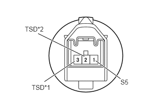
Remove the solar sensor (Click here).
Measure the resistance of the sensor.
Connect the positive (+) lead of the ohmmeter to terminal 1 and the negative (-) lead to terminal 2*2 or 3*1 of the solar sensor.
Standard Resistance
Table 9. for LHD Tester Connection
Condition
Specified Condition
1 (S5) - 3 (TSD)
Vehicle indoors
Sensor exposed to electric light
Below 1 Ω
1 (S5) - 3 (TSD)
Vehicle indoors
Sensor covered with cloth
10 kΩ or higher
Table 10. for RHD Tester Connection
Condition
Specified Condition
1 (S5) - 2 (TSD)
Vehicle indoors
Sensor exposed to electric light
Below 1 Ω
1 (S5) - 2 (TSD)
Vehicle indoors
Sensor covered with cloth
10 kΩ or higher
Table 11. Text in Illustration *1
for LHD
*2
for RHD
Note:The connection procedure for using a digital tester is shown above. When using an analog tester, connect the positive (+) lead to terminal 3*1 or 2*2 and the negative (-) lead to terminal 1 of the solar sensor.
Tip:As the inspection light is moved away from the sensor, the voltage decreases.
Use an incandescent light for the inspection. Position it about 30 cm (11.8 in.) from the solar sensor.