STOP AND START
-
CONSTRUCTION
-
The backup boost converter uses a semiconductor relay. The semiconductor relay also functions as a fuse. When overcurrent is detected, the relay is turned off to protect the circuit.
-
The backup boost converter supplies battery voltage to help make up for the voltage drop that occurs when the engine is restarted. This prevents the operation of the following equipment from being interrupted due to low battery voltage.
-
Skid Control ECU
-
Power Steering ECU Assembly
-
Steering Sensor (Spiral Cable with Sensor Sub-assembly)
-
Combination Meter Assembly
-
Remote Touch
-
Smart Door Control Receiver Assembly
-
Parking Brake ECU Assembly
-
Air Conditioning Control Assembly
-
Driving Support ECU Assembly
-
Millimeter Wave Radar Sensor Assembly
-
Lane Depeture Warning Camera
-
Blind Spot Monitor Sensor LH/RH
-
Central Gateway ECU (Network Gateway ECU)
-
Inner Rear View Mirror Assembly
-
Combination Meter Mirror ECU
-
Mayday Battery
-
Multi-display Assembly
-
Navigation ECU
-
Electric Oil Pump for AT
-
Clearance Warning ECU Assembly
-
Forward Recognition Camera
-
-
An external backup boost converter (eco run vehicle converter assembly) is used.
-
When the audio system is used during idle stop, the external backup boost converter (eco run vehicle converter assembly) compensates for the voltage drop to supplement audio playback by stabilizing the sound quality.
Figure 1. Backup Boost Converter
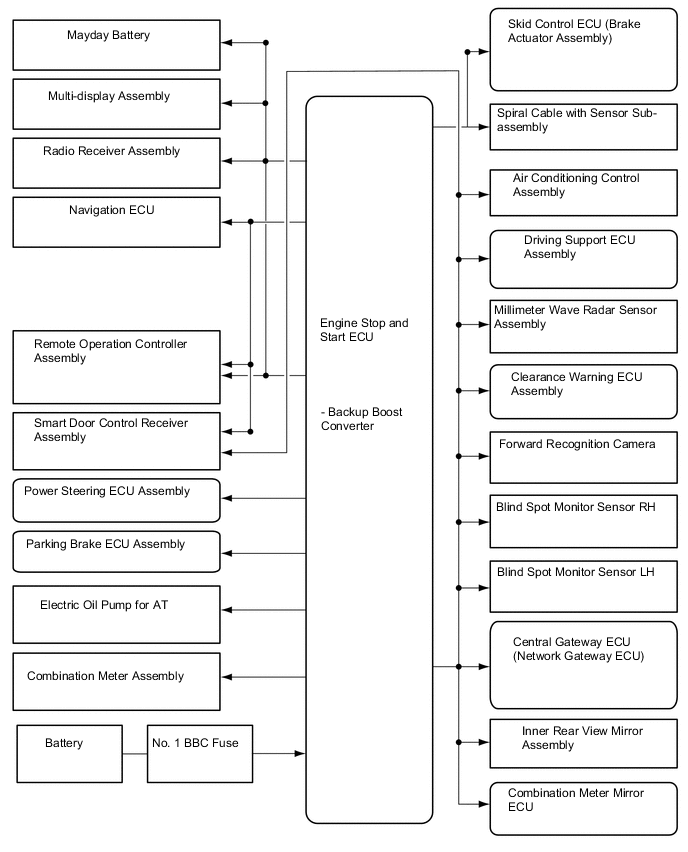
Figure 2. External Backup Boost Converter (Eco Run Vehicle Converter Assembly)
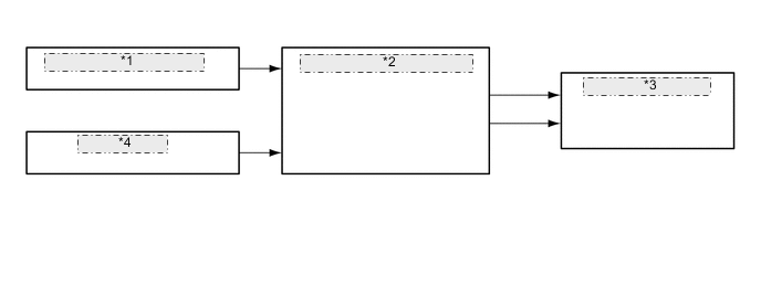
*1 Engine Stop and Start ECU *2 External Backup Boost Converter (Eco-run Veicle Converter Assembly) *3 Stereo Component Amplifier Assembly *4 No. 2 BBC Fuse
-