LIGHTING SYSTEM TERMINALS OF ECU
CHECK MAIN BODY ECU (INSTRUMENT PANEL JUNCTION BLOCK ASSEMBLY)
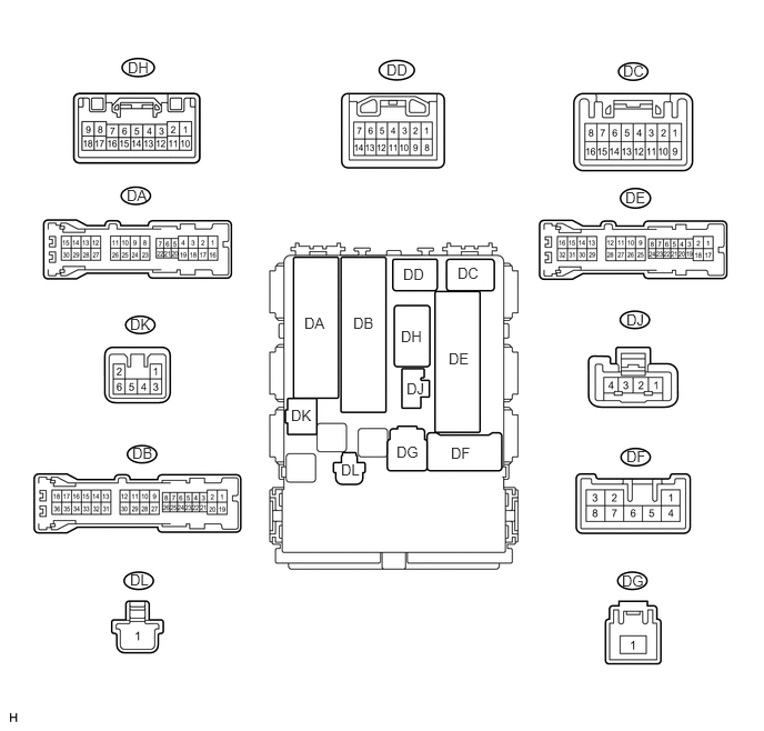
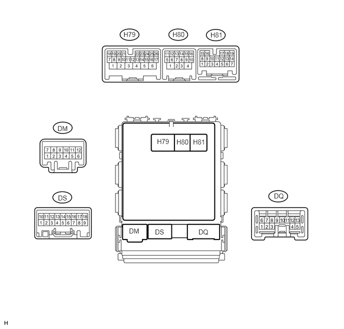
Disconnect the DB, DE, DF and H80 ECU connectors.
Measure the resistance and voltage according to the value(s) in the table below.
Terminal No. (Symbol)
Wiring Color
Terminal Description
Condition
Specified Condition
DH-12 (BECU) - Body ground
B - Body ground
Battery power supply
Always
11 to 14 V
DF-5 (ACC) - Body ground
W - Body ground
ACC power supply
Ignition switch ACC
11 to 14 V
Ignition switch off
Below 1 V
DE-28 (GND1) - Body ground
W-B - Body ground
Ground
Always
Below 1 Ω
H80-4 (GND2) - Body ground
W-B - Body ground
Ground
Always
Below 1 Ω
If the result is not as specified, there may be a malfunction on the wire harness side.
Reconnect the DB, DE, DF and H80 ECU connectors.
Measure the voltage according to the value(s) in the table below.
Terminal No. (Symbol)
Wiring Color
Terminal Description
Condition
Specified Condition
DJ-4 (HU) - DE-28 (GND1)
P - W-B
Dimmer switch high signal input
Dimmer switch in high
Below 1 V
Dimmer switch in low
11 to 14 V
H79-3 (DRLE) - DE-28 (GND1)*1,*2
H81-14 (DRLE) - DE-28 (GND1)*1,*3
W - W-B
DRL relay drive output
Daytime running light on
Below 1 V
Daytime running light off
11 to 14 V
H79-20 (HRLY) - DE-28 (GND1)
B - W-B
H-LP relay drive output
Light control switch in head
Below 1 V
Light control switch not in head
11 to 14 V
H79-21 (TAIL) - DE-28 (GND1)
W - W-B
Light control switch tail signal input
Light control switch in tail or head
Below 1 V
Light control switch in neither tail nor head
11 to 14 V
H79-22 (HF) - DE-28 (GND1)
R - W-B
Dimmer switch high flash signal input
Dimmer switch in high flash position
Below 1 V
Dimmer switch not in high flash position
11 to 14 V
H80-11 (RFGO) - DE-28 (GND1)
GR - W-B
Rear fog light relay drive output
Light control switch in head and rear fog light switch on
Below 1 V
Light control switch in head and rear fog light switch off
11 to 14 V
H80-12 (DIM) - DE-28 (GND1)
LG - W-B
Dimmer relay drive output
Dimmer switch in high or high flash
Below 1 V
Dimmer switch not in high or high flash
11 to 14 V
H80-14 (CLTE) - H80-16 (CLTB)*4, *6
W - P
Automatic light control sensor power supply output
Ignition switch off
Below 1 V
Ignition switch ON and headlight dimmer switch in AUTO position
11 to 14 V
H80-15 (CLTS) - DE-28 (GND1)*4
G - W-B*6
V - W-B*7
Automatic light control sensor signal input
Ignition switch off
Below 1 V
Automatic light control system operates
Pulse generation
(See waveform 1)
H81-9 (RFOG) - DE-28 (GND1)
SB - W-B
Rear fog light switch input
Rear fog light switch on
Below 1 V
Rear fog light switch off
11 to 14 V
H81-12 (HEAD) - DE-28 (GND1)
L - W-B
Light control switch head signal input
Light control switch in head
Below 1 V
Light control switch not in head
11 to 14 V
H81-13 (FFOG) - DE-28 (GND1)*5
B - W-B
Front fog light switch input
Front fog light switch on
Below 1 V
Front fog light switch off
11 to 14 V
H81-17 (FFGO) - DE-28 (GND1)*5
R - W-B
Front fog light relay drive output
Light control switch in tail and front fog light switch on
Below 1 V
Front fog light switch off
11 to 14 V
H81-18 (A) - DE-28 (GND1)*4
V - W-B
Light control switch AUTO signal input
Light control switch in AUTO
Below 1 V
Light control switch not in AUTO
11 to 14 V
DG-1 (TRLY) - DE-28 (GND1)
W - W-B
Battery power supply
Always
11 to 14 V
DC-5 (PKB) - DE-28 (GND1)*1
P - W-B
Parking brake switch input
Parking brake switch on
Below 1 V
Parking brake switch off
11 to 14 V
DB-33 (TRLY) - DE-28 (GND1)
GR - W-B
Clearance light LH signal output
Light control switch in tail position
11 to 14 V
Light control switch not in tail position
Below 1 V
DB-15 (TRLY) - DE-28 (GND1)
G - W-B
Clearance light RH signal output
Light control switch in tail position
11 to 14 V
Light control switch not in tail position
Below 1 V
DA-29 (TRLY) - DE-28 (GND1)
G - W-B
Taillight signal output
Light control switch in tail position
11 to 14 V
Light control switch not in tail position
Below 1 V
DS-17 (HAZ) - DE-28 (GND1)
B - W-B
Hazard warning signal switch input
Hazard warning signal switch on
Below 1 V
Hazard warning signal switch off
11 to 14 V
*1: w/ Daytime Running Light
*2: for LHD
*3: for RHD
*4: w/ Automatic Light Control System
*5: w/ Front Fog Light
*6: w/o Rain Sensor
*7: w/ Rain Sensor
-
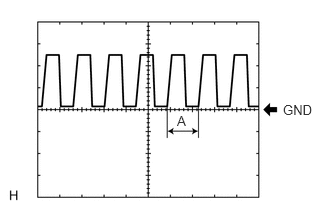
Waveform 1
Item
Content
Terminal No. (Symbol)
H80-15 (CLTS) - DE-28 (GND1)
Tool setting
5 V/DIV., 5 ms./DIV.
Condition
Ignition switch ON
Headlight dimmer switch AUTO
w/ Rain sensor
-
Rain sensor covered with a hand → Rain sensor exposed to ambient light
w/o Rain sensor
-
Automatic light control sensor covered with a hand → Automatic light control sensor exposed to ambient light
Tip:If the ambient light becomes brighter, width A becomes narrower.
CHECK HEADLIGHT LEVELING ECU (for HID Headlight)

Disconnect the A49 ECU connector.
Measure the voltage and resistance according to the value(s) in the table below.
Terminal No. (Symbol)
Wiring Color
Terminal Description
Condition
Specified Condition
A49-1 (IG) - Body ground
G - Body ground
Ignition power supply
Ignition switch off
Below 1 V
Ignition switch ON
11 to 14 V
A49-9 (E1) - Body ground
W-B - Body ground
Ground
Always
Below 1 Ω
If the result is not as specified, there may be a malfunction on the wire harness side.
Reconnect the A49 ECU connector.
Measure the resistance and voltage according to the value(s) in the table below.
Terminal No. (Symbol)
Wiring Color
Terminal Description
Condition
Specified Condition
A49-3 (B2) - A49-9 (E1)
B - W-B
Low beam headlight signal input
Low beam headlights on
Below 1 V
Low beam headlights off
11 to 14 V
A49-5 (PRST) - A49-9 (E1)
GR - W-B
Initialization signal input
Terminal LVL and terminal GND of DLC3 connected
Below 1 V
Terminal LVL and terminal GND of DLC3 not connected
Approximately 5 V
A49-6 (WNG) - A49-9 (E1)
GR - W-B
Warning indicator drive output
Warning indicator on
11 to 14 V
Warning indicator off
Below 1 V
A49-10 (RHT) - A49-9 (E1)
LG - W-B
Leveling motor RH power supply
Ignition switch off
Below 1 V
Ignition switch ON
11 to 14 V
A49-11 (LHT) - A49-9 (E1)
W - W-B
Leveling motor LH power supply
Ignition switch off
Below 1 V
Ignition switch ON
11 to 14 V
A49-12 (SBR) - A49-21 (SGR)
R - BR
Rear height control sensor power supply
Ignition switch off
Below 1 V
Ignition switch ON
4.75 to 5.25 V
A49-16 (SPDR) - A49-9 (E1)
V - W-B
Vehicle speed signal input
Vehicle is driven at approximately 20 km/h (12 mph)
Pulse generation
(See waveform 1)
A49-17 (RH+) - A49-9 (E1)
P - W-B
Leveling motor RH operation signal input
With low beam headlights on, vehicle height not changed
Below 1 V
With low beam headlights on, vehicle height changed and maintained for more than 3 seconds
1.0 to 14.4 V
A49-18 (LH+) - A49-9 (E1)
BR-W - W-B
Leveling motor LH operation signal input
With low beam headlights on, vehicle height not changed
Below 1 V
With low beam headlights on, vehicle height changed and maintained for more than 3 seconds
1.0 to 14.4 V
A49-19 (SHRL) - A49-21 (SGR)
Y - BR
Rear height control sensor signal input
Ignition switch off
Below 1 V
Ignition switch ON
0.5 to 4.5 V
A49-21 (SGR) - A49-9 (E1)
BR - W-B
Rear height control sensor ground
Always
Below 1 Ω
A49-23 (RH-) - A49-9 (E1)
W-B - W-B
Leveling motor RH ground
Always
Below 1 Ω
A49-24 (LH-) - A49-9 (E1)
B - W-B
Leveling motor LH ground
Always
Below 1 Ω
-

Waveform 1
Item
Content
Terminal No. (Symbol)
A49-16 (SPDR) - A49-9 (E1)
Tool setting
5 V/DIV., 20 ms./DIV.
Condition
Vehicle is driven at approximately 20 km/h (12 mph)
Tip:When the system is functioning normally, one wheel revolution generates 4 pulses. As the vehicle speed increases, the width indicated by (A) in the illustration narrows.
-