PURGE VALVE INSPECTION
PROCEDURE
-
INSPECT PURGE VSV
-
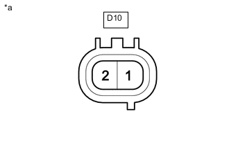
*a Component without harness connected
(Purge VSV)
Measure the resistance according to the value(s) in the table below.
Standard Resistance Tester Connection Condition Specified Condition D10-1 - D10-2 20°C (68°F) 23 to 26 Ω D10-1 - Body ground Always 10 MΩ or higher D10-1 - Body ground Always 10 MΩ or higher Tech Tips
When measuring the coil resistance make sure that the surface temperature of the purge VSV is 20°C (68°F).
If the result is not as specified, replace the purge VSV.
-
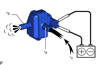
*a Port E *b Port F *c Air Apply auxiliary battery voltage between the terminals of the purge VSV and check that the following occurs when blowing air into the port E.
OK Tester Connection Condition Specified Condition D10-1 - D10-2 Battery voltage applied between the terminals Air flows from port F Battery voltage not applied between the terminals Air does not flow If the result is not as specified, replace the purge VSV.
-
-
INSPECT NO. 1 CHECK VALVE
-
Install a clean hose to the No. 1 check valve.
-
Check the operation of the No. 1 check valve.
-
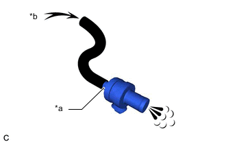
*a Purge VSV Side *b Air Blow air into the purge VSV side and check that air passes through easily.
If the result is not as specified, replace the No. 1 check valve.
CAUTION:
Do not suck air through the No. 1 check valve.
Petroleum substances inside the No. 1 check valve are hazardous to your health.
-
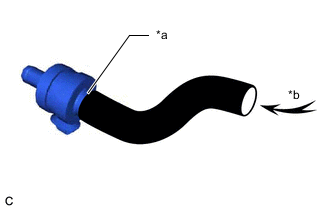
*a Intake Manifold Side *b Air Blow air into the intake manifold side and check that air passes through with difficulty.
If the result is not as specified, replace the No. 1 check valve.
-
-