CAN COMMUNICATION SYSTEM Combination Meter ECU Communication Stop Mode
| DTC Code | DTC Name |
|---|---|
| Combination Meter ECU Communication Stop Mode |
DESCRIPTION
Detection Item |
Symptom |
Trouble Area |
|---|---|---|
Combination Meter ECU Communication Stop Mode |
Either condition is met:
|
|
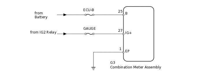
WIRING DIAGRAM
CAUTION / NOTICE / HINT
Inspect the fuses for circuits related to this system before performing the following inspection procedure.
PROCEDURE
CHECK HARNESS AND CONNECTOR (COMBINATION METER - BATTERY AND BODY GROUND)
-
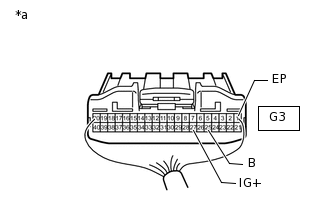
*a
Rear view of wire harness connector
(to Combination Meter Assembly)
Disconnect the G3 combination meter assembly connector.
Measure the resistance according to the value(s) in the table below.
Standard Resistance
Tester Connection
Condition
Specified Condition
G3-1 (EP) - Body ground
Always
Below 1 Ω
Measure the voltage according to the value(s) in the table below.
Standard Voltage
Tester Connection
Condition
Specified Condition
G3-25 (B) - Body ground
Always
11 to 14 V
G3-27 (IG+) - Body ground
Engine switch on (IG)
11 to 14 V
Result
Result
OK
NG
NG REPAIR OR REPLACE HARNESS OR CONNECTOR
-